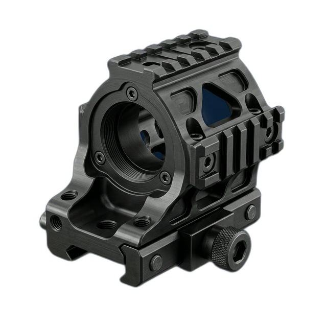
Optical Sensor Mount — 17-4 PH Stainless Steel, Condition H900
A defense integrator building an electro-optical targeting system needed a sensor mounting platform that interfaces with a gimbal assembly. Bore concentricity and perpendicularity to the mounting face were non-negotiable — any deviation would throw off optical alignment downrange.
The Challenge
Two coaxial bores needed ±0.0005″ concentricity, and the mounting face required perpendicularity within 0.0003″ to datum A. Any re-fixturing between bore and face operations would introduce enough runout to blow the concentricity callout. The material — 17-4 PH in Condition H900 — machines harder than most shops expect.
Our Approach
Single-setup 4-axis machining. We cut custom soft jaws matched to the part’s OD profile so we could reach both bores and the mounting face without unclamping. Bore and face were machined in the same operation, referencing a live datum to eliminate re-fixturing error entirely.
The Result
All 8 pieces passed first article inspection. Concentricity measured at 0.0002″ — better than the 0.0005″ callout. Full DFARS-compliant documentation shipped with the parts, including CMM data on every critical bore.
Why This Part Demands Single-Setup Machining
Optical sensor mounts for targeting systems aren’t forgiving. The sensor sits in the bore, the gimbal bolts to the face. If the bore axis isn’t dead-perpendicular to the mounting surface, the entire optical path is off — and you don’t find out until the system fails to track at range.
The drawing called out ±0.0005″ concentricity between two coaxial bores and 0.0003″ perpendicularity to datum A. That’s tight on any material. On 17-4 PH hardened to H900 (roughly 40–44 HRC), it means your tooling is fighting back the whole time. Tool deflection at those hardness levels can eat your entire tolerance budget in a single pass if you’re not careful with feeds and speeds.
The real problem, though, is fixturing. Most shops would rough the OD and bores on a lathe, then move to a mill for the mounting face features. That re-fixturing step introduces runout. Even with an indicator sweep, you’re looking at 0.0002″–0.0005″ of reintroduced error — which on this part means you’ve already used up or exceeded the concentricity budget before you even start the finish pass.
How We Held Concentricity Without Re-Fixturing
We ran the entire part in a single setup on our 4-axis mill. Here’s how we made that work:
- Custom soft jaws. We machined aluminum soft jaws contoured to the part’s OD profile. This gave us full clamping support without distorting the part, and left both bore faces and the mounting surface accessible in one setup.
- Live datum referencing. Instead of indicating off a pre-machined surface, we cut the datum face first, then immediately bored both coaxial features without releasing the part. The bore axis was established relative to the freshly machined datum — no accumulated error from re-clamping.
- Conservative finishing in H900. At 42 HRC, 17-4 PH work-hardens aggressively if you rub instead of cut. We used carbide boring bars with positive-rake inserts, held depth of cut above the minimum chip thickness, and ran through-spindle coolant to manage heat at the bore surface. Light spring passes were taken only after confirming deflection was within tolerance on the first piece.
Material: 17-4 PH, Condition H900
The customer specified 17-4 PH precipitation-hardened to Condition H900 for a reason — it’s the highest strength condition for this alloy (ultimate tensile around 190 ksi). For a sensor mount exposed to sustained vibration on a gimbal platform, you need that combination of strength and corrosion resistance. But it makes the machining harder than most austenitic stainless grades.
We sourced DFARS-compliant bar stock with full material certification, confirmed the heat lot traceability, and verified hardness on incoming material before programming. The material came in at 43 HRC — slightly above mid-range for H900 — so we adjusted our speeds down accordingly.
Passivation and Surface Treatment
Post-machining, all 8 parts were passivated per ASTM A967 using citric acid passivation. This removes free iron from the machined surfaces and restores the chromium oxide layer that gives 17-4 its corrosion resistance. No dimensional impact — passivation is a chemical process, not a coating — so we didn’t need to account for material buildup on the bore surfaces.
ITAR-Aware Handling
This project involved defense-controlled technical data. RivCut’s ITAR registration is in progress, and we handled all drawings, CAD files, and process documentation in accordance with ITAR access control requirements. Files were stored on secured systems with access limited to U.S. persons only. No technical data was shared outside the facility.
By the Numbers
Upload Your CAD File
Get instant AI pricing, a free DFM review, and full documentation on every order.
No minimums · 100% Made in USA · Never brokered · Ships anywhere in the US