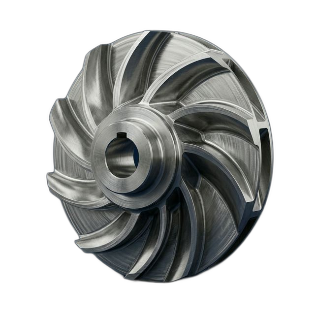
Custom Pump Impeller — Reverse Engineered from Worn Sample
A water treatment plant had a critical pump failure with a discontinued impeller — no CAD file, no drawing, no OEM support. They shipped us the corroded original and gave us 5 days before their backup pump failed. We delivered in 3.
The Challenge
No CAD data. No drawing. The original impeller was worn, corroded, and from a discontinued product line with no OEM support. We had to determine the original design dimensions from a degraded sample with complex 3D vane geometry — and do it fast enough to prevent a plant shutdown.
Our Approach
CMM-scanned the worn impeller to create a point cloud. Our programmer rebuilt the 3D CAD model from scan data, adding 0.015″ of material back to surfaces that showed wear patterns. Customer approved the CAD model in 4 hours. We machined the impeller using 5-axis simultaneous milling and started cutting the same day.
The Result
First impeller installed on Day 3 — pump restored to service before the backup pump failed. Plant avoided shutdown entirely. The customer now has a CAD file for future reorders and a spare impeller on the shelf.
When There’s No Drawing and No Time
This is the kind of call that comes in at 7 AM. The customer’s maintenance manager explained the situation: their primary process pump was down, the impeller was destroyed, and the OEM that made it went out of business years ago. They had a backup pump running, but the backup’s bearings were already showing elevated vibration. Their estimate was 5 days before the backup failed and the entire water treatment process shut down.
They overnighted the worn impeller to our shop. When it arrived, we could see why it failed — the leading edges of the vanes were eroded down to knife edges, the hub bore was corroded and oversized, and two of the six vanes had visible cavitation pitting. This wasn’t a part we could just measure with calipers and model. The original geometry had to be reconstructed from what remained.
CMM Scanning and CAD Reconstruction
We put the worn impeller on our CMM and captured a dense point cloud of the vane surfaces, hub geometry, and shroud profile. The scan gave us approximately 12,000 data points across the part. From there, our programmer did the real work — interpreting the scan data to determine what the original impeller was supposed to look like versus what wear and corrosion had done to it.
The key decisions during reconstruction:
- Vane leading edges. The worn edges had lost approximately 0.030″ of material. We rebuilt the leading edge profile using the unworn trailing edge geometry as a reference, mirroring the airfoil shape and adding 0.015″ back to account for the erosion pattern.
- Hub bore. The original bore was corroded and oversized by about 0.008″. We referenced the keyway dimensions (which were protected from corrosion) to determine the original bore diameter and fit class.
- Vane count and spacing. Six vanes, equally spaced at 60°. We confirmed this by checking the angular position of each vane root on the hub — even with wear, the root geometry was intact enough to verify even spacing.
- Shroud contour. The shroud (the disc that covers the vanes) had minimal wear since it sees less turbulence. We used the shroud scan data almost directly, with only minor smoothing of corrosion pitting.
We sent the reconstructed CAD model to the customer by noon the same day. Their maintenance engineer reviewed it against the pump housing geometry and confirmed clearances. Approval came back in 4 hours.
5-Axis Machining of Compound Vane Geometry
Pump impeller vanes aren’t flat blades — they’re compound curves that twist from the hub to the shroud. The vane angle changes continuously along its length, and the surface has to be smooth enough to maintain laminar flow. You can’t machine this geometry with 3-axis. You need 5-axis simultaneous — all five axes moving together in a coordinated toolpath so the cutter stays normal to the surface throughout the cut.
We programmed the vane surfaces using a ball-end mill with a 0.003″ stepover for the finishing pass. At that stepover, the scallop height is below 0.0005″ — essentially invisible after electropolish. The roughing strategy was adaptive — we used trochoidal toolpaths to maintain constant chip load in the deep pockets between vanes, where conventional toolpaths would cause the cutter to bury and deflect.
We machined both impellers back-to-back from 316L stainless billet. Total machining time was 14 hours per impeller — 6 hours roughing, 8 hours finishing the vane surfaces.
Balancing and Final Inspection
An unbalanced impeller will destroy pump bearings in weeks — which is exactly the failure mode the customer was trying to avoid. We balanced both impellers to ISO 1940 G6.3, which is the standard grade for general-purpose pump rotors. The balance report ships with the part so the customer’s maintenance team can verify it during installation.
We ran a CMM comparison between the finished impeller and the original scan data. This overlay report shows how closely the new part matches the reconstructed design intent — all vane surfaces came in within ±0.005″, and the hub bore and keyway hit ±0.001″.
Electropolish for Flow and Corrosion Resistance
The finished impellers were electropolished to achieve two things: a smoother flow surface (reducing turbulence and improving pump efficiency) and enhanced corrosion resistance. Electropolishing removes a thin layer of surface material in a controlled electrochemical bath, eliminating machining marks and micro-burrs that can initiate corrosion in water/wastewater service. The resulting surface is passive and smooth — ideal for a 316L component in continuous water contact.
The Customer Now Owns Their Supply Chain
Before this project, the customer was dependent on an OEM that no longer exists. Now they have a full CAD model of their impeller, validated against the original part, stored on their server. If they need another impeller in two years or ten years, they send us the file and we cut it. No reverse engineering, no scanning — just a straight reorder. That’s the real value of this project beyond the emergency turnaround.
By the Numbers
Upload Your CAD File
Get instant AI pricing, a free DFM review, and full documentation on every order.
No minimums · 100% Made in USA · Never brokered · Ships anywhere in the US