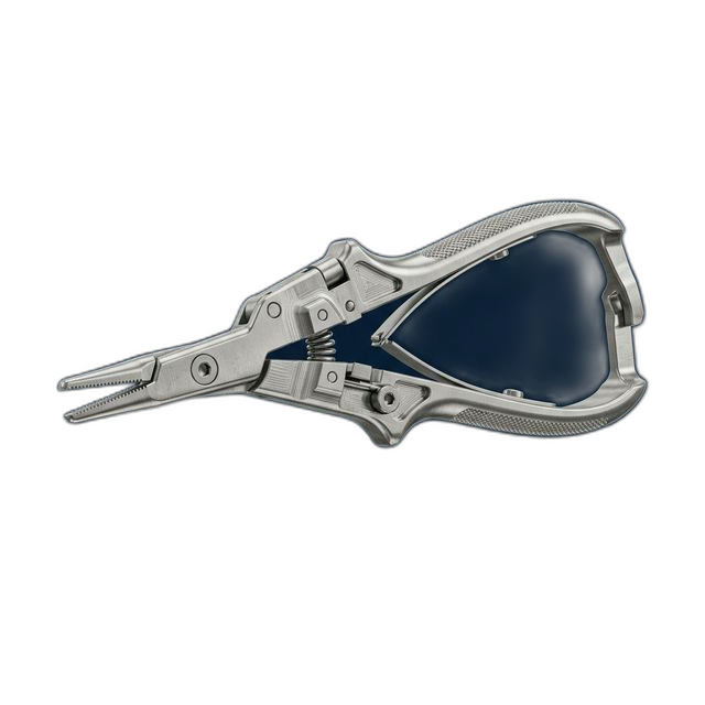
Surgical Instrument Prototype — 316L Stainless Steel
A medical device company developing a next-generation laparoscopic surgical instrument needed functional prototypes for surgeon evaluation and FDA pre-submission testing. The instrument jaw had compound curves, a cam slot mechanism, and a pivot bore that demanded ±0.0005″ to ensure smooth articulation under surgical loads.
The Challenge
The instrument jaw combined compound 3D contours with a precision cam slot and pivot bore. The pivot bore needed ±0.0005″ to prevent play during articulation — any slop and the surgeon loses tactile feedback. Wall thickness at the jaw tip was just 0.030″ in 316L stainless, requiring both milling and turning operations without distorting the thin section.
Our Approach
5-axis simultaneous milling for the jaw contours, precision turning on the shaft, and a custom Delrin conforming nest to support the thin jaw during finishing. Pivot bore machined last to prevent distortion from prior operations. Electropolished to Ra < 8 μin for biocompatibility.
The Result
Surgeon feedback from the 2nd iteration led to a jaw angle change — RivCut turned V3 in 3 days. Final version cleared FDA pre-submission review. The customer moved to a production run of 200 units with the same shop that built their prototypes.
Why Surgical Instruments Are Difficult to Machine
Surgical instruments look deceptively simple in CAD. A jaw, a shaft, a pivot pin. But the functional requirements create a machining problem where everything is coupled. The pivot bore controls articulation feel — if it’s 0.001″ oversize, the jaw has perceptible play that surgeons will reject immediately. The cam slot controls jaw opening angle and force profile — its geometry has to match the simulation model within ±0.001″ or the instrument doesn’t perform as designed.
Then there’s the material. 316L stainless steel is the standard for surgical instruments — implant-grade per ASTM F138, excellent corrosion resistance, proven biocompatibility. But it’s also gummy, work-hardens aggressively, and generates significant heat during cutting. On a part with 0.030″ wall thickness at the jaw tip, heat buildup causes thermal expansion that shifts dimensions during the cut. You can be holding ±0.0005″ on one feature while the heat from that operation distorts the feature you cut five minutes ago.
How We Solved It
Our approach was built around operation sequencing and workholding — the two factors that determine whether a thin-wall surgical instrument comes out right or goes in the scrap bin.
- 5-axis simultaneous milling for jaw contours. The compound curves on the jaw couldn’t be reached with 3-axis toolpaths without multiple setups. We ran 5-axis simultaneous to machine the entire jaw geometry in a single setup, eliminating setup-to-setup error accumulation. Tool engagement was kept light — 0.005″ radial depth of cut — to manage heat generation in the thin jaw section.
- Custom Delrin conforming nest. We machined a negative-form fixture from Delrin that cradled the jaw contour during finishing operations. The Delrin is soft enough to avoid marking the 316L surface but rigid enough to prevent the 0.030″ walls from deflecting under cutting forces. Without this fixture, the thin jaw tip would chatter and produce an unacceptable surface finish.
- Pivot bore machined last. This is counterintuitive — most shops machine precision bores early in the process while the part is still rigid. But on this instrument, the stress redistribution from removing material on the jaw side would pull the bore out of round. By machining the pivot bore as the final operation, after all roughing and semi-finishing was complete, we eliminated post-machining distortion. The bore came in at ±0.0003″ — well within the ±0.0005″ callout.
- Precision turning on the shaft. The instrument shaft required concentric features with tight runout. We turned the shaft on our CNC lathe with live tooling, then transferred the part to the 5-axis mill for jaw machining. The transfer datum was a precision ground mandrel that maintained < 0.0002″ TIR between operations.
Electropolishing for Biocompatibility
The finished instruments were electropolished to Ra < 8 microinch. Electropolishing isn’t just cosmetic on a surgical instrument — it’s a functional requirement. The process removes the outer layer of disturbed metal (the Beilby layer) left by machining, eliminates micro-burrs that could harbor bacteria, and creates a passive chromium oxide surface that resists corrosion in the autoclave environment.
We coordinated electropolishing with our certified finishing partner. Each batch was processed with documented parameters — current density, electrolyte temperature, immersion time — and the electropolish certification was included in the documentation package. For a device heading toward FDA submission, this traceability matters.
3 Iterations in 3 Weeks
Medical device development is iterative by nature. The customer’s design team was working from finite element analysis and ergonomic models, but nothing replaces putting a physical instrument in a surgeon’s hand. V1 validated the cam mechanism and pivot feel. Surgeon feedback from V2 evaluation sessions identified that the jaw angle needed a 4° change for better tissue visualization. The customer sent revised CAD on a Monday morning — V3 parts were on their bench by Thursday.
Each iteration included 4 pieces: two for surgeon evaluation, one for destructive testing, and one retained as a reference sample. We maintained the same fixtures across all three iterations, modifying only the toolpaths for geometry changes. This continuity meant V2 and V3 didn’t start from scratch — setup time dropped by 60% after the first run.
Documentation for FDA Pre-Submission
The customer was preparing a pre-submission (Q-Sub) package for FDA. Their regulatory team needed machining documentation that demonstrated process control, not just final dimensions. We provided dimensional reports for each iteration showing CMM data on all critical features, material certification for 316L per ASTM A276 with full heat and lot traceability, Certificate of Conformance, and electropolish certification with process parameters.
When the FDA reviewer asked about manufacturing consistency across prototypes, the customer had three iterations of CMM data showing the pivot bore holding ±0.0003″ across all 12 parts. That’s the kind of data that builds confidence in a pre-submission meeting.
By the Numbers
Upload Your CAD File
Get instant AI pricing, a free DFM review, and full documentation on every order.
No minimums · 100% Made in USA · Never brokered · Ships anywhere in the US