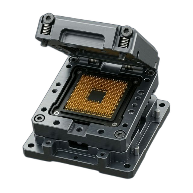
Gas Delivery Manifold — 316L Stainless Steel for Plasma Etch Chamber
A semiconductor equipment manufacturer needed a gas delivery manifold for a plasma etch tool. The manifold distributes process gases to 12 injection points around a chamber lid — flow uniformity directly affects etch uniformity across the wafer. Zero contamination tolerance. Every particle is a potential killer defect.
The Challenge
Twelve internal gas channels must have identical cross-sectional area — ±0.0005″ on bore diameter — to ensure equal gas distribution to each injection point. Internal surface finish must be ≤16 Ra to prevent particle generation. All internal surfaces must be electropolished, and the finished part must contain zero cutting fluid residue and zero particulate. In semiconductor, a single contaminated manifold can scrap an entire wafer lot worth millions.
Our Approach
Gundrilled primary channels, then CNC-finished the distribution ports for maximum bore-to-bore consistency. Used semiconductor-grade cutting fluid — DI water-based, particle-free — throughout the entire process. Measured each bore with an air gauge at ±0.0001″ resolution. Ultrasonic cleaned in DI water bath, nitrogen dried, and double-bagged in Class 100 cleanroom packaging.
The Result
All 4 manifolds passed flow uniformity testing on the first run. The customer confirmed <1% flow variation across all 12 injection points — etch uniformity improved versus their previous vendor’s manifolds. Zero particle excursions reported during chamber qualification.
Why This Part Demands Semiconductor-Grade Precision
A gas delivery manifold looks like plumbing — but in a plasma etch tool, it’s the single most critical component for process uniformity. The manifold sits on top of the chamber lid and splits incoming process gas (SF6, CF4, or other fluorine-based etch chemistries) into 12 individual streams that feed injection points evenly spaced around the chamber perimeter. If any channel delivers more or less gas than its neighbors, the etch rate varies across the wafer. On a 300mm wafer running advanced-node features, even 2% non-uniformity can push devices out of spec at the edge.
The material choice is non-negotiable: 316L stainless steel for chemical compatibility with fluorine-based plasma chemistries. Fluorine radicals are among the most aggressive chemical species in semiconductor processing — they attack most metals and polymers. 316L’s chromium-nickel-molybdenum composition forms a passive oxide layer that resists fluorine attack, but only if the surface is properly electropolished to remove embedded particulate and create a smooth, chemically inert boundary.
The Contamination Control Problem
In semiconductor fabrication, contamination is the enemy. A single metallic particle lodged inside a gas channel can break free during processing, travel with the gas stream into the chamber, and land on a wafer. That particle becomes a killer defect — shorting a circuit, blocking an etch, or nucleating an unwanted film. One contaminated manifold can destroy hundreds of wafers before the source is identified. The customer’s spec was absolute: zero particle contamination, zero organic residue, zero cutting fluid carryover.
Most machine shops use conventional cutting fluids — petroleum-based emulsions loaded with sulfur and chlorine additives. These fluids leave microscopic residue in blind holes and internal channels that no standard cleaning process can fully remove. In a vacuum chamber running at 10−6 Torr, those residues outgas and contaminate the process environment. The customer’s previous vendor had delivered manifolds that passed visual inspection but caused particle excursions during chamber qualification — they traced it back to cutting fluid residue embedded in the bore surfaces.
How We Solved It
We built the entire machining plan around contamination prevention, not just contamination removal after the fact:
- Semiconductor-grade cutting fluid. We ran DI water-based, particle-free cutting fluid for every operation. No petroleum. No sulfur. No chlorine additives. This eliminates the contamination source rather than trying to clean it out later.
- Gundrilling plus CNC finishing. The primary channels were gundrilled to establish straight, consistent bores. Then each distribution port was CNC-finished with controlled feed rates to prevent smearing or work-hardening the bore surface. This two-stage approach gave us the bore-to-bore consistency the flow uniformity spec demands.
- Air gauge metrology at ±0.0001″ resolution. Standard bore micrometers don’t have the resolution for this work. We measured each of the 12 bores per manifold (48 total measurements across the lot) using an air gauge system that detects diameter variation down to 0.0001″. Every bore was verified to be within the 0.125″ ±0.0005″ callout.
- Electropolish to ≤10 Ra. All internal channel surfaces were electropolished to remove the disturbed metal layer from machining and create a smooth, passive surface. The spec called for ≤16 Ra — we achieved ≤10 Ra across all channels, reducing the surface area available for particle adhesion and outgassing.
- Multi-stage ultrasonic cleaning and cleanroom packaging. After electropolish, every manifold went through a multi-stage ultrasonic clean in heated DI water, followed by nitrogen blow-dry in a particle-controlled environment. Parts were double-bagged in Class 100 cleanroom bags with desiccant. From final clean to sealed bag, parts never touched an uncontrolled surface.
Flow Uniformity Results
The customer installed all 4 manifolds into their plasma etch tools and ran flow verification tests before chamber qualification. The results confirmed <1% flow variation across all 12 injection points on every manifold — within spec on the first test, with no shimming, no rework, and no leaks at the VCR fittings.
More importantly, the etch uniformity data from their first qualification wafers showed measurable improvement over the previous vendor’s manifolds. The customer attributed the improvement to two factors: tighter bore-to-bore consistency (our air gauge data showed ±0.0002″ actual variation vs. the ±0.0005″ spec), and the cleaner internal surfaces that eliminated micro-turbulence from surface roughness.
What the Customer Said
“We’ve been burned by shops that treat semiconductor parts like standard machine work. RivCut understood that the cleaning and contamination protocol is just as important as the machining tolerances. These manifolds qualified on the first chamber pump-down — no particle excursions, no outgassing spikes. That saved us two weeks of troubleshooting.”
By the Numbers
Upload Your CAD File
Get instant AI pricing, a free DFM review, and full documentation on every order.
No minimums · 100% Made in USA · Never brokered · Ships anywhere in the US