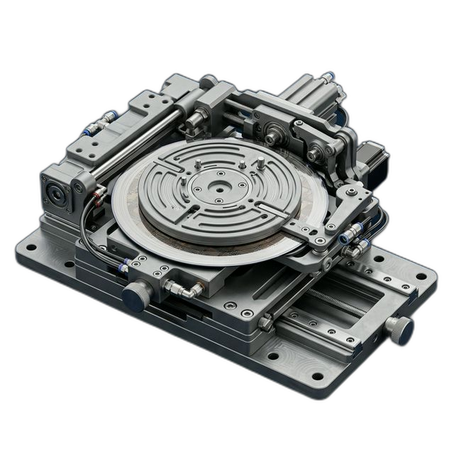
Wafer Handling Fixture — 6061-T6 Aluminum with Hard Anodize
A semiconductor fab tooling team needed custom wafer handling fixtures for their automated transfer system. The fixtures hold 300mm wafers during wet-clean processing — flatness and edge registration are critical to prevent wafer slip or contact damage. A dropped wafer is a $25,000+ loss before it even reaches lithography.
The Challenge
Flatness across the 14″ diameter fixture face must be within 0.0005″ total. Three wafer registration pads must be coplanar within 0.0002″. Hard anodize (Type III) adds 0.001″ per side — pre-machining dimensions must compensate for coating buildup on critical surfaces without compromising final geometry.
Our Approach
Stress-relieved billet before first cut. Vacuum fixture for distortion-free clamping on a 14″ diameter disc. Machined registration pads 0.0005″ proud to compensate for anodize buildup on non-critical surfaces while masking pads during coating to hold final dimension. Verified flatness on granite surface plate with electronic indicator.
The Result
All 10 fixtures met flatness spec post-anodize. Zero wafer slip events reported after installation into the automated wet-clean system. The customer ordered 20 more fixtures for their second wet-clean tool within 6 weeks.
Why Wafer Handling Fixtures Are Deceptively Difficult
A wafer handling fixture looks like a simple flat disc with three small pads. But the tolerances tell a different story. A 300mm silicon wafer is approximately 0.775mm (0.030″) thick — a fragile, perfectly flat disc worth tens of thousands of dollars in accumulated process value by the time it reaches wet-clean. The fixture must support the wafer without deflection, locate it precisely for robotic pickup, and survive repeated exposure to aggressive cleaning chemistries like SC-1 (NH4OH/H2O2), SC-2 (HCl/H2O2), and dilute HF.
If the fixture face isn’t flat within spec, the wafer rocks on the high points. A rocking wafer shifts during the high-velocity spin rinse cycle, and the robot’s end effector can’t acquire it at the expected position. The result: the robot either misgrabs the wafer edge (causing edge chips that propagate into yield-killing cracks) or drops it entirely. In a production fab running 24/7, a single fixture-related wafer breakage event triggers an equipment shutdown, a contamination investigation, and a root cause analysis that can take days.
The Hard Anodize Compensation Problem
Hard anodize (Type III, per MIL-A-8625) is the right coating for this application — it gives 6061-T6 aluminum the chemical resistance to survive thousands of wet-clean cycles without degradation. But hard anodize isn’t paint. The coating grows into the aluminum substrate and out from the surface simultaneously, adding approximately 0.001″ per side (0.0005″ penetration, 0.0005″ buildup). On a part where total flatness is 0.0005″, uncontrolled anodize buildup can consume the entire tolerance budget.
The conventional approach — machine to final dimension and let the anodize land where it lands — doesn’t work here. If the fixture face gains 0.001″ of anodize coating unevenly (which happens when coating thickness varies across a 14″ diameter surface), the flatness goes out of spec. And the three registration pads that locate the wafer must be at an exact height relative to the fixture face — if the anodize shifts their height by even 0.0003″, the wafer sits too high and the robot’s vacuum pickup can’t get a reliable seal.
How We Solved It
We designed the machining and coating process together, not sequentially:
- Stress relief before machining. We started with stress-relieved 6061-T6 billet. Residual stress in aluminum plate stock causes flatness distortion as material is removed — on a 14″ diameter disc machined from one side, an un-relieved billet can bow 0.003″ or more. Stress-relieving the billet first removed that variable from the equation.
- Vacuum fixturing for distortion-free clamping. Mechanical clamps on a thin disc create localized pressure points that distort the part during machining. The surface reads flat on the CMM while clamped, then springs out of spec when released. We used a full-face vacuum fixture that distributes holding force evenly across the entire back surface — what you measure on the machine is what you get off the machine.
- Selective anodize masking on registration pads. The three registration pads were machined 0.0005″ proud of the surrounding surface, then masked during hard anodize so no coating was deposited on the pad faces. The non-critical surrounding surfaces received the full 0.001″/side anodize buildup, which brought them flush with the proud pads. The result: registration pads at exact final dimension with bare aluminum contact surfaces (acceptable for this application since the pads never contact wet chemistry), and a fully anodized fixture body for chemical protection.
- Pre- and post-anodize CMM verification. We ran full flatness maps on every fixture before and after anodize processing. The pre-anodize data confirmed the machining was within spec. The post-anodize data verified that the coating process didn’t push any fixture out of the 0.0005″ flatness envelope. This dual verification caught one fixture that came back from anodize with a 0.0004″ bow — still in spec, but we flagged it for the customer’s awareness.
- Granite surface plate final verification. As a belt-and-suspenders check, we verified every fixture on a calibrated granite surface plate using an electronic indicator with 0.00005″ resolution. The surface plate is flat to 0.000050″ across 36″ — it’s the ultimate truth reference. All 10 fixtures confirmed within spec.
Why the Reorder Happened
The customer installed the 10 fixtures into their first wet-clean tool and ran qualification wafers. Zero wafer slip events. Zero edge chips from mishandling. Zero robot acquisition failures. The fixtures performed exactly as specified through over 2,000 wet-clean cycles in the first month, with no measurable degradation of the hard anodize coating.
Six weeks later, the customer ordered 20 more fixtures for their second wet-clean tool — same spec, same process. They also asked us to quote a modified version for their acid-bench application, where the chemistry is more aggressive and the anodize spec changes to a thicker build.
What the Customer Said
“We’ve tried three shops for these fixtures. Two of them couldn’t hold the flatness post-anodize — they’d machine it flat, send it out for coating, and it would come back bowed. RivCut figured out the masking and compensation strategy that actually works. Zero wafer events since we installed them. That’s all that matters.”
By the Numbers
Upload Your CAD File
Get instant AI pricing, a free DFM review, and full documentation on every order.
No minimums · 100% Made in USA · Never brokered · Ships anywhere in the US