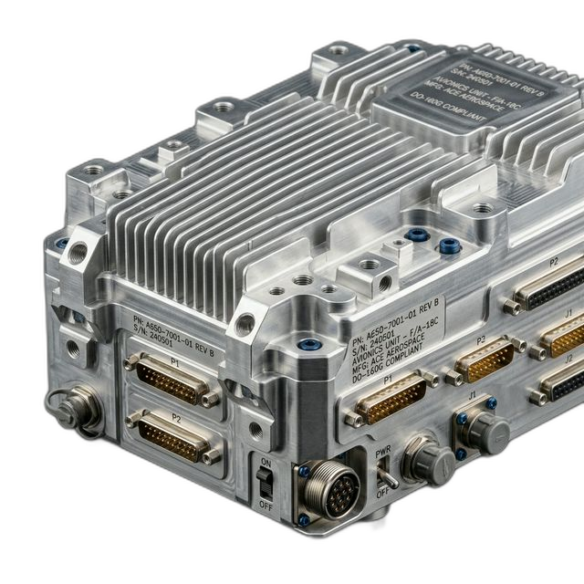
Avionics Housing — 7075-T6 Aluminum with EMI Shielding Pockets
A Tier 1 aerospace supplier needed a line-replaceable avionics housing machined from solid 7075-T6 billet. Tight positional tolerances on connector cutouts, thin-wall pockets for EMI gasket channels, and a 4-day delivery window.
The Challenge
The customer’s previous vendor couldn’t hold ±0.0005" on the connector mounting face while keeping the EMI gasket channel walls under 0.040" thick. Parts were failing incoming inspection at the connector interface.
Our Approach
We ran a DFM review before cutting. Identified that the original toolpath order was causing thermal distortion in the thin walls. Re-sequenced machining operations: rough the pockets first, stress-relieve, then finish the connector bore pattern in a single setup.
The Result
All 12 housings passed first article inspection with zero deviations. The connector pattern hit ±0.0003" true position — better than the ±0.0005" callout. Delivered in 4 business days with full AS9100D-aligned documentation.
Why This Part Is Hard to Machine
Avionics housings look simple on the outside — a rectangular box with a lid. But the internal geometry tells a different story. This housing had 14 connector cutouts on three faces, each with ±0.0005" true position requirements relative to a common datum. The EMI gasket channel ran the full perimeter with 0.040" wall thickness and 0.020" floor radius.
The problem: when you machine thin walls out of solid billet, residual stress in the aluminum causes the walls to deflect as material is removed. If you machine the connector bores before the walls stabilize, the entire pattern shifts. That’s exactly what happened with the customer’s previous vendor — their parts were 0.003" out of position on the connector face.
How We Solved It
Our programmer reviewed the part and flagged the risk during DFM. We recommended a three-phase machining strategy:
- Phase 1 — Rough and relieve. Rough all pockets to within 0.020" of final dimension. Remove the part from the fixture and let it sit overnight so residual stresses equalize.
- Phase 2 — Re-datum and finish walls. Re-indicate the part on a vacuum fixture to remove clamping distortion. Finish the EMI channels and outer walls to final spec.
- Phase 3 — Bore the connector pattern. Machine all 14 connector cutouts in a single setup, referencing the freshly finished datum surfaces. This eliminates any cumulative error from the roughing phase.
We also ran a test cut on a scrap billet first to validate the approach before committing the production material. That test cut confirmed the strategy — the connector pattern came in at ±0.0003" true position.
Surface Finish and Post-Processing
The housing required Alodine (chromate conversion coating per MIL-DTL-5541) for corrosion protection without adding thickness to the connector interfaces. We coordinated the Alodine processing with our finishing partner and included it in the 4-day delivery window.
The EMI gasket channel surfaces were finished to 16 Ra to ensure proper gasket compression. Mating surfaces on the connector face were held to 32 Ra per the customer’s drawing callout.
What the Customer Said
“Our previous shop couldn’t figure out why the connectors kept coming in out of position. RivCut caught it in the DFM review before they even started cutting. Every part passed incoming inspection. We moved our next three orders to them.”
By the Numbers
Upload Your CAD File
Get instant AI pricing, a free DFM review, and full documentation on every order.
No minimums · 100% Made in USA · Never brokered · Ships anywhere in the US