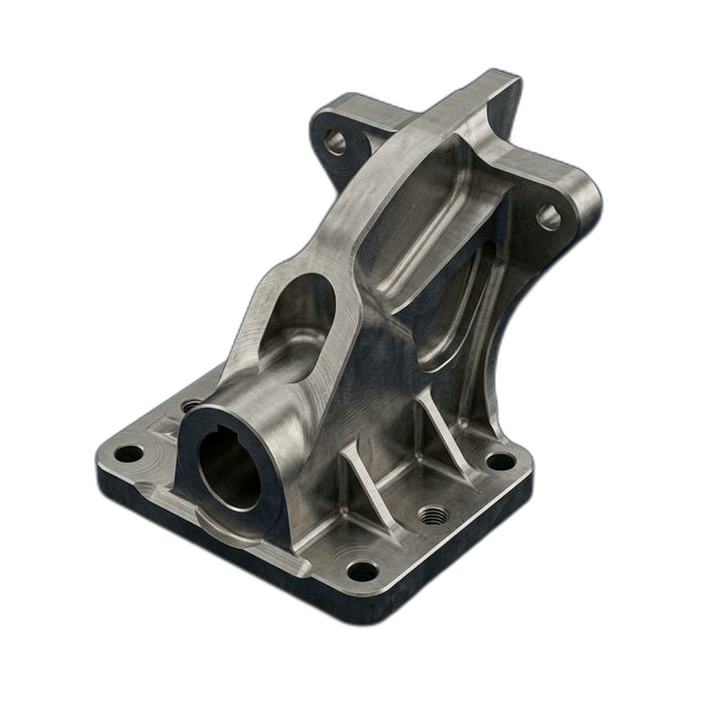
Engine Inlet Guide Vane — Inconel 718
A turbine engine MRO company needed replacement inlet guide vanes for a legacy engine program. The OEM no longer supplies the part. Complex airfoil geometry with thin trailing edges and fatigue-critical root fillets — all machined from Inconel 718.
The Challenge
Airfoil profile tolerance ±0.002″ with trailing edge thickness down to 0.020″. Inconel 718 work-hardens aggressively — conventional machining causes surface damage that creates stress risers in fatigue-critical parts. The root fillet radius is critical for high-cycle fatigue life.
Our Approach
5-axis simultaneous milling with constant-engagement trochoidal toolpaths. Ceramic roughing at 800+ SFM, carbide finishing at controlled chip load. Through-spindle coolant at 1000 PSI. Trailing edge machined climb-only to prevent work-hardening on the thin section.
The Result
All 6 vanes within profile tolerance. Trailing edge held at 0.020″ ±0.002″. Customer’s metallurgical lab confirmed zero surface damage in micro-section analysis — no recast layer, no work-hardened zone beyond spec.
Why This Part Is Hard to Machine
Inconel 718 is one of the most demanding materials in CNC machining. It retains its strength at temperatures up to 1300°F, which is exactly why it’s specified for hot-section turbine components. But that same high-temperature strength means the material doesn’t soften at the cutting zone the way steel or aluminum does. The heat stays in the tool instead of transferring into the chip.
The bigger problem is work-hardening. When Inconel is machined with insufficient chip load — or when the tool rubs instead of cutting cleanly — the surface hardens dramatically. On a fatigue-critical part like an inlet guide vane, a work-hardened layer acts as a stress riser that can initiate cracks under high-cycle loading. The trailing edge at 0.020″ thick is especially vulnerable: any surface damage on a section that thin can propagate through the entire cross-section.
The root fillet where the airfoil meets the platform is another critical zone. This fillet carries the highest bending stress during engine operation. Scallop marks or tool witness lines from poor surface finish act as fatigue crack initiation sites. The fillet has to be blended smooth with no discontinuities.
How We Solved It
We programmed the entire airfoil as a 5-axis simultaneous toolpath with constant tool engagement. Here’s why each decision mattered:
- Ceramic roughing at 800+ SFM. Ceramic inserts thrive at high surface speeds where Inconel actually becomes easier to cut. We ran trochoidal (constant-engagement) roughing toolpaths that maintain consistent chip load throughout the cut. No dwelling, no rubbing, no work-hardening. Material removal rate was 3× faster than conventional carbide roughing.
- Through-spindle coolant at 1000 PSI. High-pressure coolant directed through the tool tip does two things: it breaks chips into manageable segments (preventing chip re-cutting, which causes work-hardening) and it evacuates heat from the cutting zone before it can soak into the workpiece surface.
- Climb-only trailing edge machining. The trailing edge was finished exclusively in the climb milling direction. In conventional milling, the cutter starts with zero chip thickness and rubs before it bites — that rubbing work-hardens the surface. Climb milling engages with full chip thickness from the start, producing a clean shear cut with no rubbing on the finished surface.
- Continuous 5-axis root fillet blend. The root fillet was machined with a ball endmill in a single continuous 5-axis sweep. No stepover lines, no scallop marks, no tool entry/exit witness marks. The result is a smooth, stress-free fillet surface with consistent roughness across the entire transition.
Material and Post-Processing
The Inconel 718 billet was procured per AMS 5662 with full material certification and heat lot traceability. The parts were delivered as-machined — the customer handles post-machining heat treatment (solution treat and age) at their own qualified facility. Surface roughness measurements on the airfoil surfaces were included with each vane’s inspection package.
What the Customer Said
“We’d been turned down by three shops on this job. Two said they couldn’t hold the trailing edge thickness, and one quoted 8 weeks. RivCut delivered all six vanes in 10 days and our met lab couldn’t find any surface anomalies in the micro-sections. We’re sending them the next batch of stator vanes.”
By the Numbers
Upload Your CAD File
Get instant AI pricing, a free DFM review, and full documentation on every order.
No minimums · 100% Made in USA · Never brokered · Ships anywhere in the US