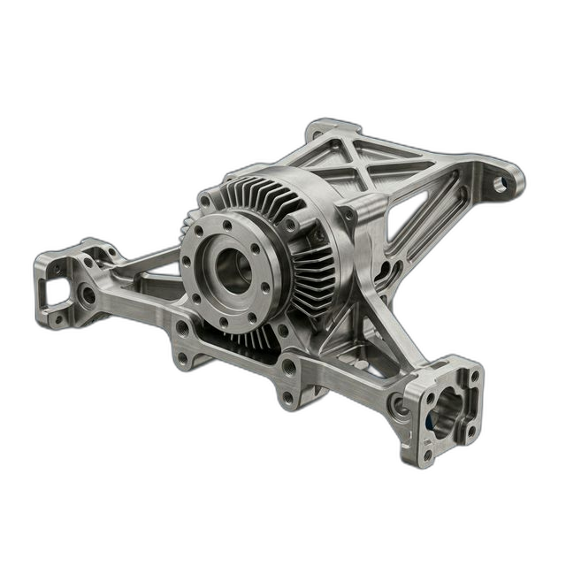
UAV Motor Mount Assembly — 7075-T6 Aluminum
A defense-adjacent drone company building a Group 3 UAV (55+ lbs) needed motor mount plates for their quad-motor propulsion system. Each mount must absorb vibration while maintaining precise motor alignment to prevent propeller-induced yaw drift.
The Challenge
Four motor mounting bolt patterns must be parallel within 0.001″ to each other and perpendicular to the airframe interface within 0.0005″. Vibration isolation slots (0.040″ wide, 1.5″ deep) act as tuned dampers — slot geometry must be exact to hit the target resonant frequency. Weight cannot exceed 285 grams per mount.
Our Approach
All four motor patterns machined in a single setup on a multi-angle fixture to guarantee inter-pattern parallelism. Vibration slots cut with a slotting endmill in a single plunge to prevent slot width variation. Final weight verified on calibrated scale.
The Result
278 grams per mount — 7 grams under the 285g target. Flight testing confirmed vibration reduction vs. the previous design. Zero propeller yaw drift detected during autonomous GPS waypoint testing. Customer ordered 20 more sets.
Why This Part Is Hard to Machine
A motor mount for a multi-rotor UAV has to do two contradictory things: it must be rigid enough to maintain precise motor alignment under thrust loads, and it must be compliant enough to isolate motor vibration from the airframe. The vibration isolation slots are what make this part work — and what make it difficult to machine.
The slots are 0.040″ wide and 1.5″ deep, giving them a 37.5:1 depth-to-width ratio. At that aspect ratio, the slotting endmill deflects under cutting forces, which causes the slot to widen at the top and narrow at the bottom. If the slot geometry is wrong, the tuned damping frequency shifts and the mount either transmits too much vibration (reducing sensor accuracy and airframe fatigue life) or is too compliant (allowing motor misalignment under thrust).
The parallelism requirement between the four motor bolt patterns is the other critical challenge. On a quad-motor UAV, if any motor is tilted relative to the others, it produces a yaw moment that the flight controller must constantly correct. That correction burns battery and reduces endurance. The customer’s previous mounts were machined in multiple setups, and the accumulated setup error was enough to cause measurable yaw drift during GPS waypoint navigation.
How We Solved It
The fixturing strategy was the key decision on this job. We designed a multi-angle fixture that presents all four motor pattern surfaces to the spindle in a single setup:
- Single-setup multi-pattern machining. The fixture holds the mount blank at the compound angle needed so that all four motor mounting surfaces can be machined without re-fixturing. Because the spindle is the reference for all four patterns, the inter-pattern parallelism is limited only by machine repeatability (typically under 0.0002″ on our equipment) rather than setup accuracy.
- Single-plunge vibration slots. Each vibration isolation slot was cut with a slotting endmill in a single plunge pass. This eliminates the slot width variation that occurs when you make multiple axial passes — each re-engagement slightly widens the slot due to tool deflection on entry. A single plunge at controlled feed rate keeps the slot geometry consistent from top to bottom.
- Airframe interface perpendicularity. The airframe mounting face was machined as the final operation, with the part still fixtured from the motor pattern setup. This guarantees the 0.0005″ perpendicularity between the motor patterns and the airframe interface, since both features reference the same fixture datum.
- Weight verification. Each completed mount was weighed on a calibrated scale. Final weight came in at 278 grams — 7 grams under the 285g target. The weight savings came from optimized pocket depths that our programmer identified during toolpath development, where the drawing allowed slightly deeper pockets without affecting structural integrity.
Surface Finish and Post-Processing
The mounts received Type III hard anodize for wear resistance at the motor interface. Hard anodize adds approximately 0.001″ per side, which was accounted for in the machining dimensions on the motor mounting surfaces. The bolt holes were masked during anodizing to maintain proper clearance for the motor mounting hardware.
What the Customer Said
“We were chasing yaw drift for months and assumed it was a flight controller tuning issue. Turned out our old mounts had enough angular error between motor positions to create a constant yaw bias. RivCut’s single-setup approach eliminated it completely. First flight with the new mounts — zero drift on a 12-waypoint autonomous mission. We ordered 20 more sets for our pre-production run.”
By the Numbers
Upload Your CAD File
Get instant AI pricing, a free DFM review, and full documentation on every order.
No minimums · 100% Made in USA · Never brokered · Ships anywhere in the US