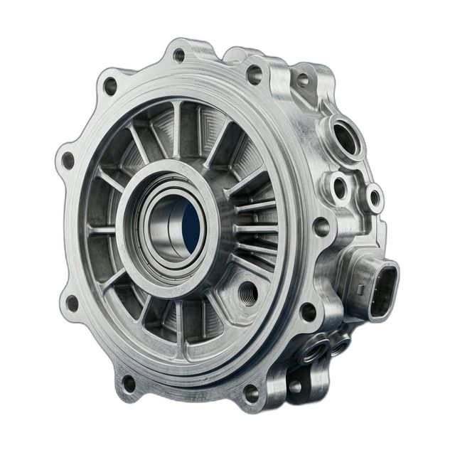
EV Motor End Bell — 6061-T6 Aluminum with Integrated Cooling Fins
An electric motor startup building prototype traction motors for a light commercial EV needed end bells that close the motor housing and support the output-side bearing. Bearing bore alignment relative to the stator bore centerline determines motor efficiency, noise, and bearing life — concentricity is everything.
The Challenge
Bearing bore concentricity to the spigot (stator bore pilot) within 0.0003" — this is the motor’s rotor-to-stator alignment. Bearing bore diameter H7 tolerance for press-fit bearing. Bolt circle ±0.005" on 12 mounting bolts. Cooling fin geometry on the external face for convective heat dissipation.
Our Approach
Bearing bore and spigot machined in the same setup on the lathe — both features turned from the same datum (spindle centerline) guaranteeing concentricity. Cooling fins machined on mill in second setup. Bolt circle drilled last using the spigot as the centering reference.
The Result
Concentricity measured at 0.0002" (spec 0.0003"). Motor assembly achieved target efficiency of 96.2% (spec >95%). Bearing noise below 45 dB at rated speed. Customer ordered a second batch for durability test motors.
Why End Bell Concentricity Determines Motor Performance
In an electric motor, the air gap between the rotor and stator is typically 0.5–1.0mm. That gap must be uniform around the entire circumference — if the rotor is offset to one side, the uneven magnetic field creates radial forces that cause vibration, increased bearing load, and reduced efficiency. The end bell is what positions the output-side bearing, and the bearing is what positions that end of the rotor. So the concentricity between the end bell’s bearing bore and its spigot (the pilot diameter that registers into the stator housing) directly controls the rotor-to-stator alignment.
At 0.0003" concentricity, the rotor offset is small enough that the air gap variation is less than 5% of the nominal gap — within the range where efficiency impact is negligible and bearing life is not compromised. Go above that, and you start to see measurable efficiency loss and NVH (noise, vibration, harshness) issues that are unacceptable in a commercial vehicle application.
The bearing bore itself has an H7 tolerance for the press-fit bearing installation. H7 provides enough interference to prevent the bearing outer race from spinning in the bore under load, but not so much interference that the press force distorts the race and increases bearing preload. This is a precision fit that requires careful bore finishing — not just diameter accuracy, but roundness and surface finish as well.
How We Guaranteed Concentricity
The key to achieving 0.0003" concentricity is eliminating setup transfers between the two critical features. If you machine the bearing bore on a lathe and then move the part to a mill to machine the spigot, you introduce runout from the mill’s chuck, vise, or fixture — typically 0.0005–0.001" even with careful indicating. That alone would blow the concentricity spec.
Our approach: machine both features in a single lathe setup.
- Setup 1 (Lathe): Bearing bore + spigot. The end bell was chucked on the lathe and both the bearing bore (internal) and the spigot diameter (external) were turned from the same spindle centerline datum. Since both features are generated by the same rotational axis, their concentricity is limited only by the lathe’s spindle runout — typically 0.0001" on our equipment. The bearing bore was finish-bored with a single-point boring bar for H7 size and roundness control.
- Setup 2 (Mill): Cooling fins. The external cooling fin geometry was machined on the mill using the spigot as the locating datum in a collet fixture. The fins are non-critical dimensionally — they function by increasing surface area for convective cooling — so the setup transfer to the mill introduced no risk to the critical concentricity relationship already established on the lathe.
- Setup 3 (Mill): Bolt circle. The 12-hole bolt circle was drilled in the same mill setup as the cooling fins, using the spigot as the centering reference. The ±0.005" true position on the bolt circle is generous compared to the bore concentricity, so this is a straightforward drilling operation. We drilled all 12 holes in a single indexing cycle for consistent position accuracy.
Material Selection: 6061-T6 Aluminum
The customer specified 6061-T6 for two reasons: weight and thermal conductivity. At 167 W/m·K, 6061-T6 conducts heat significantly better than cast iron or steel — important for an end bell that needs to dissipate motor heat through the cooling fins on its external face. The motor generates heat primarily from copper losses in the stator windings and iron losses in the lamination stack. That heat conducts through the housing and end bell, and must be rejected to the air (or to a liquid cooling jacket on the housing) to keep the motor within its thermal limits.
6061-T6 is also easier to machine than 7075-T6, producing better surface finishes in the bore without requiring as many spring passes. For the H7 bearing bore, this translates to less time on the lathe and a more consistent finish across the 8-part lot.
Surface Finish: Alodine MIL-DTL-5541
The end bells received Alodine chromate conversion coating per MIL-DTL-5541. Alodine provides corrosion protection with negligible thickness build-up — less than 0.0001" — so there’s no dimensional impact on the bearing bore, spigot, or bolt circle. It also provides a conductive surface, which is important for grounding the motor housing in the vehicle’s electrical system. Anodize would create an insulating layer that would need to be masked off the mating surfaces.
CMM Inspection
Every end bell was CMM inspected for concentricity (bore to spigot), bearing bore diameter and cylindricity, and bolt circle true position. The concentricity measurement was performed by scanning 36 points on the bore ID and 36 points on the spigot OD, then computing the center offset between the two best-fit circles. All 8 parts measured 0.0002" or better on concentricity — well within the 0.0003" spec. Bearing bore cylindricity was within 0.0001" across the lot.
By the Numbers
Upload Your CAD File
Get instant AI pricing, a free DFM review, and full documentation on every order.
No minimums · 100% Made in USA · Never brokered · Ships anywhere in the US