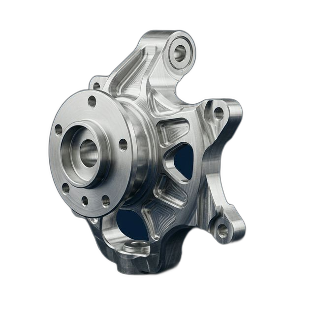
Suspension Knuckle Prototype — 7075-T6 Aluminum, Topology-Optimized Geometry
An EV startup developing their skateboard platform needed prototype front suspension knuckles for ride and handling development. The topology-optimized design features organic shapes and internal pockets that reduce weight 31% vs. the cast iron baseline — but the complex geometry is challenging to machine from billet.
The Challenge
Topology-optimized geometry with 5+ undercuts, thin organic webs, and non-planar surfaces. Bearing bore ±0.0005" for wheel bearing press fit. Steering arm ball joint taper bore must match a standard taper gauge within 0.001". Caliper mounting face flatness 0.001". Minimum 3 setups required.
Our DFM Insight
We recommended adding 2mm fillets to three stress-riser zones identified in the topology optimization where wall intersections were too sharp for safe machining. The customer’s FEA confirmed <2% stress impact. This prevented potential cracking during machining of the thin webs.
The Result
Finished knuckles weighed 4.2 lbs vs. 6.1 lbs for the cast iron baseline — a 31% reduction. Ride and handling testing confirmed suspension geometry targets met. Customer proceeding to cast aluminum tooling for production based on machined prototype validation.
Why Topology-Optimized Parts Are Difficult to Machine from Billet
Topology optimization produces organic, bone-like shapes that place material only where stress paths require it. The result is a part with thin webs, internal pockets, undercuts, and non-planar surfaces — geometries that are natural for casting or additive manufacturing but challenging for subtractive machining. A conventional knuckle design might require two setups; the topology-optimized version needed at least three, with 5-axis access for the undercuts.
The difficulty isn’t just reaching all the features — it’s maintaining dimensional control across multiple setups on a part whose thin, flexible webs deflect under cutting forces. The bearing bore is the most critical feature: ±0.0005" controls the wheel bearing press fit. If the bore is oversize, the bearing spins in the housing and fails. If undersize, the press force damages the bearing during installation. And this bore must be machined after the surrounding material has already been pocketed away, leaving minimal support structure.
The caliper mounting face adds another constraint: 0.001" flatness determines the brake caliper alignment to the rotor. If the caliper is cocked, the brake pads wear unevenly and pulling occurs during braking — a safety issue that would compromise the ride/handling test program.
DFM Review: Adding Fillets to Prevent Cracking
During our DFM review, we identified three locations where the topology optimization produced sharp internal corners at wall intersections. These corners create stress concentrations during machining — as the endmill removes the surrounding material, the remaining web is loaded in bending by cutting forces. At a sharp corner, the stress concentration factor can be 3× or higher, which can initiate cracks in the thin aluminum webs.
We recommended adding 2mm fillets at these three locations. The customer ran FEA on the modified geometry and confirmed less than 2% increase in peak stress under the design load cases — well within the safety factor. The fillets also improved the tool access for the finishing passes, reducing cycle time by approximately 15 minutes per part.
Machining Strategy: 3-Setup Process
- Setup 1: Hub face and bearing bore. The bearing bore is the primary datum for the entire knuckle. We machined the hub face and bore first, establishing the wheel centerline. The bore was finish-bored to ±0.0005" with a single-point boring bar for roundness and size control. The hub face was fly-cut for flatness.
- Setup 2: Caliper mount and steering arm. With the part fixtured on the bearing bore (using an expanding mandrel for concentricity), we machined the caliper mounting face to 0.001" flatness and the ball joint taper bore. The taper was checked against a standard gauge for contact pattern — minimum 80% contact across the taper surface.
- Setup 3: 5-axis profiling of organic surfaces. The topology-optimized pockets, webs, and undercuts were machined using 5-axis simultaneous milling. Light finishing passes with reduced feed rates on the thin web sections to minimize deflection. The DFM fillets we added enabled smoother tool transitions and eliminated the stress-riser risk.
Material Selection: 7075-T6 Aluminum
The customer selected 7075-T6 for the prototype knuckles because weight reduction is critical for EV range. Every pound of unsprung mass (weight not supported by the suspension springs) has a disproportionate effect on ride quality and handling response. The 7075-T6 billet knuckle at 4.2 lbs is 1.9 lbs lighter per corner than the cast iron baseline — that’s 7.6 lbs of unsprung mass removed from the front axle.
For production, the customer plans to use A356-T6 cast aluminum, which is less expensive and easier to cast than 7075. But for prototype validation, billet 7075-T6 provides the closest strength proxy — it’s actually stronger than the production casting will be, so the prototype testing is conservative.
Surface Finish: Hard Anodize Type III
The knuckles received Type III hard anodize for wear resistance at the bearing interface. Hard anodize builds a 0.002" oxide layer that is extremely hard (60–70 Rockwell C equivalent) and wear-resistant. This is important at the bearing bore, where the press-fit bearing will be installed and potentially removed during the test program. Without hard anodize, repeated bearing installation and removal would gall the aluminum bore surface, changing the interference fit.
We compensated the bearing bore diameter for the anodize build-up: the pre-anodize bore was machined 0.002" oversize on diameter (0.001" per side), so the final anodized bore matched the ±0.0005" drawing callout.
CMM Inspection
All 4 knuckles were CMM inspected on the critical bores and faces. Bearing bore diameter, roundness, and cylindricity were measured per the H7 fit specification. Caliper mount flatness was measured across a 4-point grid. Ball joint taper bore was verified by taper gauge contact check with dye transfer. The CMM data package and DFM markup were shipped with every knuckle.
By the Numbers
Upload Your CAD File
Get instant AI pricing, a free DFM review, and full documentation on every order.
No minimums · 100% Made in USA · Never brokered · Ships anywhere in the US