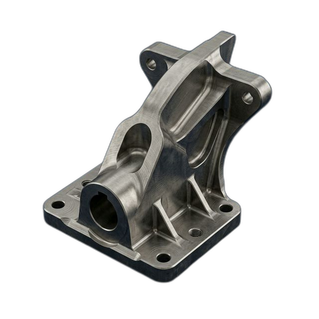
Encrypted Radio Chassis — 6061-T6 with EMI Shielding
A communications OEM building encrypted tactical radios for a DoD program needed machined chassis with integrated EMI shielding features. The chassis houses RF circuitry — any RF leakage compromises encryption security and causes electromagnetic interference with adjacent systems in the vehicle or dismounted configuration.
The Challenge
EMI gasket channels require consistent depth (±0.001″) and width (±0.002″) around the entire perimeter for proper gasket compression. 23 board-level RF compartment walls (0.060″ thick) must be perpendicular to the chassis floor within 0.002″ for board grounding. SMA connector bores need ±0.001″ for press-fit interference.
Our Approach
Continuous toolpath gasket channel machining with no plunge marks. RF compartment walls machined with an alternating-side slotting strategy to prevent wall deflection. SMA bores step-drilled then reamed for consistent press-fit. ITAR-aware handling with NDA signed.
The Result
All 15 chassis passed RF shielding effectiveness testing with >80 dB attenuation at 18 GHz. Zero gasket leak points detected. Customer noted that their previous vendor averaged 3–4 rework items per lot — this lot shipped with zero rework.
Why EMI Chassis Machining Is Different from Standard Enclosure Work
A typical electronics enclosure needs to hold a board, route some cables, and look presentable. An encrypted radio chassis has to do all of that while functioning as a Faraday cage. Every surface, every joint, every connector penetration is a potential RF leak path. At 18 GHz — the upper end of the Ku-band where many tactical radio systems operate — RF energy will find its way through gaps as small as a few thousandths of an inch.
The chassis design addresses this with three integrated shielding features: a continuous EMI gasket channel around the lid perimeter, 23 internal RF compartment walls that isolate individual circuit stages, and precision-bored SMA connector ports. Each feature has a different machining challenge, and all of them have to be right on the same part.
The customer had been through two previous vendors on this chassis. Both produced parts that required rework — gasket channels with inconsistent depth (causing gasket leak points), compartment walls that weren’t perpendicular enough for reliable board grounding, and SMA bores that were either too tight (cracking the connector during press-fit) or too loose (creating an RF leak at the connector-chassis interface). They averaged 3–4 rework items per lot of 15.
Gasket Channel: Zero Plunge Marks, Consistent Compression
The EMI gasket sits in a channel machined around the entire lid perimeter. The gasket must compress evenly when the lid is fastened down — any variation in channel depth creates a low-compression zone where RF energy leaks through. The specification was ±0.001″ depth and ±0.002″ width around the full perimeter.
- Continuous toolpath strategy. We programmed the gasket channel as a single continuous toolpath that ramps into the material at the start and ramps out at the end. No mid-channel plunge entries. Plunge marks create localized depth variations — even a 0.0005″ plunge mark can become a gasket leak point at 18 GHz. The continuous path eliminates this failure mode entirely.
- Gasket channel depth mapping. After machining, we ran a CMM depth map of the gasket channel at 24 points around the perimeter. Every point was within ±0.0006″ of nominal — well within the ±0.001″ callout. The depth map shipped with each chassis as part of the documentation package.
RF Compartment Walls: 23 Thin Walls, All Perpendicular
The 23 RF compartment walls are 0.060″ thick and must be perpendicular to the chassis floor within 0.002″. These walls serve two functions: they isolate RF stages from each other (preventing cross-coupling between, say, the local oscillator and the IF stage), and they provide grounding surfaces for the circuit boards that press against them when installed.
- Alternating-side slotting strategy. Machining a 0.060″ wall by slotting from one side only creates unbalanced cutting forces that push the wall away from the cutter. Over the depth of the wall, this deflection accumulates and the wall ends up leaning. We programmed an alternating strategy: cut one side to partial depth, switch to the other side, then return to the first side for the next depth increment. This balances the cutting forces and keeps the wall straight.
- Perpendicularity verification. We measured wall perpendicularity on the CMM using a best-fit plane on the wall surface referenced to the chassis floor datum. All 23 walls across all 15 chassis were within 0.0015″ — comfortably inside the 0.002″ spec.
SMA Connector Bores: Press-Fit Precision
SMA connectors are pressed into the chassis wall, and the bore diameter determines the interference fit. Too tight, and the connector cracks or the bore galls during insertion. Too loose, and there’s a gap between the connector body and the chassis wall — an RF leak path right at the point where the signal enters or exits the enclosure.
- Step-drill and ream process. We step-drilled the SMA bores to within 0.005″ of final diameter, then reamed to final size in a single pass. Reaming after step-drilling produces a consistent bore diameter and surface finish that drilling alone cannot achieve. The final bore diameter was held to ±0.0005″ across all connector locations on all 15 chassis.
Material: 6061-T6 Aluminum
6061-T6 is the standard chassis material for tactical radio enclosures because of its combination of properties: excellent electrical conductivity (40% IACS) for EMI shielding, good machinability for the complex internal features, and light weight for man-portable applications. The electrical conductivity matters because the chassis itself is a critical part of the shielding system — the aluminum walls, gasket contact surfaces, and connector interfaces all need to conduct RF energy to ground rather than letting it radiate.
We sourced DFARS-compliant 6061-T6 plate with full material certification. The Alodine conversion coating applied post-machining preserves the bare aluminum’s conductivity at all mating surfaces — unlike anodize, which is an insulator and would defeat the grounding function of the compartment walls and gasket channels.
Alodine Finish: MIL-DTL-5541
All 15 chassis received Alodine (chromate conversion coating) per MIL-DTL-5541 Class 1A. This is the only acceptable finish for an EMI chassis — it provides corrosion protection while maintaining electrical conductivity at all contact surfaces. The gasket channel, compartment wall tops, and SMA bore surfaces all need bare-metal conductivity for proper grounding and shielding. Anodize would insulate these surfaces and destroy the shielding effectiveness.
ITAR-Aware Handling
This project involved defense-controlled technical data for a DoD encrypted communications program. RivCut’s ITAR registration is in progress, and we handled all drawings, CAD files, and process documentation in accordance with ITAR access control requirements. An NDA was signed before any technical data was received. Files were stored on secured systems with access limited to U.S. persons only. No technical data was shared outside the facility.
By the Numbers
Upload Your CAD File
Get instant AI pricing, a free DFM review, and full documentation on every order.
No minimums · 100% Made in USA · Never brokered · Ships anywhere in the US