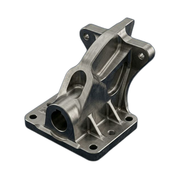
Missile Fin Actuator Bracket — Titanium 6Al-4V
A defense prime subcontractor needed actuator mounting brackets for a guided missile fin assembly. The bracket transfers actuator forces to the fin pivot and must withstand 50g launch loads and aerodynamic heating to 600°F — any dimensional variation in bore-to-bore spacing causes binding in the actuator linkage.
The Challenge
Thin web sections (0.040″) between the actuator mount bores and fin pivot bore are prone to chatter during machining. Under 50g launch loads, any dimensional variation in bore-to-bore spacing causes binding in the actuator linkage. The bore spacing required ±0.0005″ true position — on titanium, where tool deflection and heat generation fight you at every step.
Our Approach
5-axis machining with custom soft jaws supporting both sides of the thin webs during cutting. High-speed finishing at 40,000+ RPM micro-finish passes to prevent chatter on thin sections. Both bore sets machined in a single setup to guarantee position. ITAR-aware handling throughout the process.
The Result
All 10 brackets passed first article inspection. Bore spacing measured ±0.0003″ — well within the 0.0005″ callout. Zero chatter marks on thin web sections. Customer confirmed smooth actuator assembly operation with no binding.
Why Thin Webs in Titanium Change Everything
Actuator brackets for missile fin assemblies don’t have the luxury of overbuilt cross-sections. Every gram matters in a guided munition — the bracket has to be as light as possible while transferring actuator forces cleanly to the fin pivot. That means thin webs between bore features, and thin webs in Ti 6Al-4V are where most shops get into trouble.
The problem is twofold. First, titanium’s low thermal conductivity means heat concentrates at the cutting edge and the workpiece rather than evacuating through chips. On a 0.040″ web, that heat has nowhere to go — the web itself becomes a heat sink, which can cause localized thermal growth during machining and distort the bore spacing you’re trying to hold. Second, thin webs deflect under cutting forces. Conventional roughing strategies that work fine on a 0.250″ wall will chatter a 0.040″ web into scrap before you even get to the finish pass.
The drawing called out ±0.0005″ true position on the bore-to-bore spacing between actuator mount bores and the fin pivot bore. That’s the number that determines whether the actuator linkage articulates smoothly or binds under load. At 50g launch acceleration, a binding actuator linkage doesn’t just cause a performance degradation — it causes a guidance failure.
How We Eliminated Chatter on 0.040″ Webs
We ran this part on our 5-axis mill and built the entire process around keeping the thin webs stable during machining:
- Custom soft jaws with web support. We machined aluminum soft jaws that clamped the part’s OD profile and included standoff features that contacted both sides of the thin web sections. This turned a flexible, chatter-prone feature into a supported structure during the entire cutting operation.
- High-speed micro-finish strategy. Instead of conventional finishing feeds and speeds, we ran the finish passes at 40,000+ RPM with very light radial engagement. At those spindle speeds, the chip load per tooth drops low enough that cutting forces on the thin web are negligible — the web doesn’t deflect, and there’s no harmonic excitation to trigger chatter.
- Single-setup bore machining. Both the actuator mount bores and the fin pivot bore were machined in one setup. No unclamping, no re-indicating, no re-fixturing error. The bore-to-bore spacing was cut relative to a single coordinate system established from the fixture datum.
- Thermal management. Through-spindle coolant with high-pressure delivery (1,000 PSI) kept heat from building up in the web sections during roughing. We also programmed coolant-off dwell periods between roughing and finishing to let the part equalize thermally before taking the final bore passes.
Material: Titanium 6Al-4V
Ti 6Al-4V is the default choice for missile airframe components where you need high strength-to-weight ratio and elevated temperature capability. With a UTS around 130 ksi and continuous service to 600°F, it handles both the structural loads of fin actuation and the aerodynamic heating environment of supersonic flight. But it’s demanding to machine — low thermal conductivity, work-hardening tendency, and a strong affinity for tool materials that causes built-up edge if your speeds and feeds aren’t dialed in.
We sourced DFARS-compliant Ti 6Al-4V bar stock with full material certification and confirmed the alloy chemistry and mechanical properties against AMS 4928 before releasing to production. Incoming hardness was verified at 34 HRC, consistent with annealed condition per the material spec.
Passivation and Surface Treatment
All 10 brackets were passivated per ASTM A967 after machining. For titanium, passivation removes any embedded iron contamination from tooling contact and ensures the native titanium oxide layer is intact across all machined surfaces. This is especially important on the bore surfaces where the actuator pins interface — any ferrous contamination would create a galvanic couple and initiate corrosion in the field.
ITAR-Aware Handling
This project involved defense-controlled technical data for a guided missile subsystem. RivCut’s ITAR registration is in progress, and we handled all drawings, CAD files, and process documentation in accordance with ITAR access control requirements. Files were stored on secured systems with access limited to U.S. persons only. No technical data was shared outside the facility.
By the Numbers
Upload Your CAD File
Get instant AI pricing, a free DFM review, and full documentation on every order.
No minimums · 100% Made in USA · Never brokered · Ships anywhere in the US