IoT Gateway Heat Sink Enclosure — 6061-T6 Aluminum
A Bay Area IoT startup needed a functional enclosure prototype for their industrial gateway device. The enclosure doubles as a heat sink — internal fin geometry dissipates heat from the main processor and PoE module. They had a board bring-up deadline in 8 days for a customer demo.
The Challenge
Internal heat sink fins (1mm thick, 15mm tall, 0.8mm spacing) deflect under cutting forces, and the tight spacing makes chip evacuation difficult. PCB mounting bosses must align with the board’s mounting holes to ±0.005" so the PoE connector lines up perfectly with the enclosure’s Ethernet cutout.
Our Approach
Machined fins with a 1mm single-flute endmill at high RPM and low depth of cut to minimize cutting forces. Used air blast for chip evacuation instead of flood coolant to prevent coolant from getting trapped between fins. PCB bosses and connector cutout machined in the same setup to guarantee alignment.
The Result
Board fit perfectly on first assembly. Thermal testing showed processor temperature 12°C cooler than the previous sheet-metal enclosure. The startup nailed their customer demo and came back for a production run of 200 units.
Why This Part Is Hard to Machine
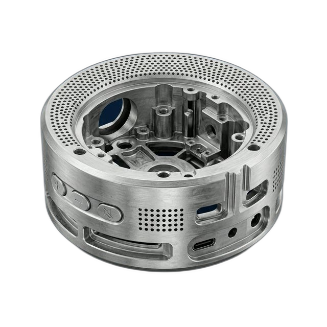
The enclosure looks like a standard aluminum box from the outside, but flip it over and you’re looking at a dense array of heat sink fins machined from solid billet. Each fin is just 1mm thick and 15mm tall, separated by 0.8mm channels. At those aspect ratios, the fins want to deflect under cutting forces — and if they vibrate, you get chatter marks that destroy the surface finish and reduce thermal contact area.
The second challenge is chip evacuation. With 0.8mm spacing between fins, aluminum chips have nowhere to go. Flood coolant — the default approach — actually makes it worse because it traps chips between the fins instead of flushing them out. Packed chips re-cut and generate heat, which can warp the thin fins and ruin dimensional accuracy.
On top of the fin geometry, the enclosure has four PCB mounting bosses and an Ethernet connector cutout that must align to ±0.005". That’s tighter than typical consumer specs because the PoE connector on the board has to mate flush with the enclosure wall — any misalignment and the RJ45 jack either won’t seat or creates an air gap that ruins the IP rating.
How We Solved It
We ran a free DFM review the day the customer submitted their STEP file and flagged both risks before quoting. Here’s the machining strategy we used:
- Single-flute strategy for thin fins. We used a 1mm single-flute endmill running at high RPM with a shallow depth of cut (0.5mm per pass). Single-flute tools produce less radial cutting force than multi-flute tools, which keeps the thin fins from deflecting. We machined the fins from the outside in to keep maximum material support for as long as possible.
- Air blast instead of flood coolant. We switched from flood coolant to targeted air blast for the fin machining operations. The high-velocity air stream blows chips up and out of the channels without trapping them. This kept the fin surfaces clean and prevented re-cutting.
- PCB bosses and cutout in one setup. We machined the four mounting bosses and the Ethernet connector cutout in the same fixture setup without re-clamping. This eliminated any positional error from re-fixturing and guaranteed the boss-to-cutout alignment the PoE connector requires.
Surface Finish and Post-Processing
The customer wanted a professional, product-like appearance for their demo — not a raw machined look. We bead blasted all external surfaces for a uniform matte texture, then sent the parts for black Type II anodize. The anodize adds a 0.0002"–0.0005" layer, which we accounted for on the PCB boss diameters and connector cutout so the board still fit after finishing.
The internal fin surfaces were left as-machined. Anodize would have added thermal resistance between the fins and the air, reducing the heat sink’s effectiveness — we flagged this in the DFM review and the customer agreed to mask the fin area.
What the Customer Said
“We were two weeks from our biggest customer demo and our previous vendor said they couldn’t do the fins. RivCut quoted us the same day, flagged the anodize issue we hadn’t considered, and delivered four perfect enclosures with two days to spare. The board dropped right in. We nailed the demo and closed the deal.”
By the Numbers
Upload Your CAD File
Get instant AI pricing, a free DFM review, and full documentation on every order.
No minimums · No setup fees between iterations · Free DFM review · Ships anywhere in the US