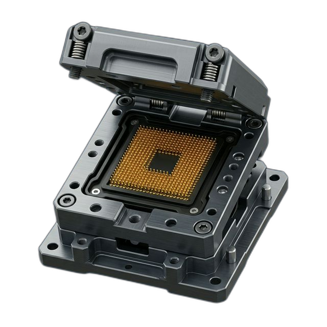
Burn-In Test Socket Housing — PEEK for Automotive IC Qualification
A semiconductor test equipment company building custom burn-in sockets for automotive-grade IC qualification needed a socket housing that holds IC packages at 150°C for 1,000+ hours under electrical bias. The housing must be dimensionally stable at elevated temperature, electrically insulating, and hold 144 spring probe contacts in precise position — at room temperature and at burn-in temperature.
The Challenge
A 144-pin contact array with ±0.001″ hole position accuracy — each hole locates a spring probe contact. At 150°C, PEEK expands: hole positions must be compensated for thermal expansion at operating temperature. Hole diameter ±0.0005″ for contact retention force consistency. The socket must survive 2,000+ hours at 150°C without dimensional drift or material degradation.
Our Approach
Calculated PEEK CTE (2.6 × 10⁻⁵ /°F) and pre-compensated all 144 hole positions for 150°C operating temperature. Each hole micro-drilled with a 0.020″ carbide drill then reamed for diameter control. Hole positions verified on CMM at room temperature — customer verified at 150°C on their optical metrology system.
The Result
All pin positions verified within spec at 150°C. Contact retention force measured ±5% across all 144 pins (spec: ±10%). Zero socket-related failures in a 2,000-hour burn-in qualification run.
Why Burn-In Sockets Demand Thermal Compensation
Burn-in testing is the gatekeeper for automotive-grade semiconductor reliability. Every IC destined for an automotive application — engine controllers, ADAS sensors, infotainment processors — must survive 1,000+ hours at elevated temperature under electrical bias to screen out infant mortality failures. The burn-in socket is the interface between the IC package and the test board. It holds the IC in place, makes electrical contact through 144 spring probes, and must maintain reliable contact at 150°C for the entire duration of the test.
The socket housing material is PEEK (polyether ether ketone) — one of the few polymers that can operate continuously at 480°F (250°C) without degradation. PEEK is electrically insulating at 1016 Ω·cm resistivity, has low outgassing (critical in burn-in ovens where outgassing deposits on test boards), and maintains its mechanical properties at elevated temperature. But PEEK has a significant coefficient of thermal expansion: 2.6 × 10⁻⁵ /°F — roughly twice that of aluminum. At 150°C, the socket housing has grown measurably from its room-temperature dimensions.
The Thermal Expansion Problem
A 144-pin IC package has contacts on a precise grid — typically 0.5mm or 0.8mm pitch. The spring probes in the socket must align with every contact pad on the IC to within a few thousandths of an inch. If you machine the socket holes at room temperature using the nominal IC pad positions, the holes will expand outward as the socket heats to 150°C. The pins at the center of the array may still align, but the pins at the edges will be shifted by the cumulative thermal expansion across the array. Edge pins lose contact or make intermittent contact, causing false test failures that waste time and scrap good ICs.
The challenge is compounded by PEEK’s anisotropic expansion behavior — the material can expand differently depending on the fiber fill and grain direction. The customer’s previous vendor had machined sockets without thermal compensation, and they were seeing 15–20% false failure rates on edge pins during burn-in — a massive yield loss that was costing them thousands of dollars per burn-in cycle.
How We Solved It
We treated the socket housing as a precision metrology problem, not a simple drilling job:
- CTE-compensated hole positions. We calculated the thermal expansion of PEEK from room temperature (68°F) to operating temperature (302°F / 150°C) using the published CTE of 2.6 × 10⁻⁵ /°F. For each of the 144 holes, we computed the position offset from the array center and scaled it inward by the expansion factor. The result: holes are drilled at room-temperature positions that are slightly tighter than the IC pad pitch, but when the socket expands at 150°C, the holes move to the correct location.
- Micro-drilling with carbide tooling. Each of the 144 holes starts as a 0.020″ diameter bore. Drilling holes this small in PEEK requires carbide micro-drills running at high speed with controlled peck cycles to prevent the polymer from melting around the drill (PEEK has a glass transition temperature of 289°F — heat buildup during drilling can cause the material to flow and close the hole). We ran compressed air blast cooling instead of liquid coolant to avoid contaminating the socket.
- Reaming for diameter consistency. After drilling, each hole was reamed to final diameter using a precision carbide reamer. The reaming operation controls hole diameter to ±0.0005″, which directly controls the interference fit with the spring probe contacts. Too loose and the contact falls out; too tight and it can’t be inserted without damage. The ±5% retention force uniformity the customer measured confirms our diameter consistency.
- CMM verification of all 144 holes per socket. Every socket — all 10 units — was inspected on the CMM with all 144 hole positions measured. That’s 1,440 position measurements across the lot. We provided the customer with the room-temperature position data and the calculated hot-state positions. They verified the hot-state positions on their optical metrology system at 150°C — every pin within spec.
Burn-In Qualification Results
The customer loaded all 10 sockets into their burn-in ovens and ran a 2,000-hour qualification at 150°C with electrical bias. The results spoke for themselves: zero socket-related failures across the entire run. Contact retention force held at ±5% across all 144 pins (spec was ±10%) — meaning every spring probe maintained consistent pressure against the IC pads for the full 2,000 hours.
Compared to their previous vendor’s sockets (which had no thermal compensation), the false failure rate dropped from 15–20% to zero. The customer estimated that the improved sockets saved them over $50,000 per burn-in cycle in avoided re-testing and false scrap.
What the Customer Said
“We’d been fighting edge-pin contact failures for months and couldn’t figure out why. RivCut showed us the thermal expansion math and proved that our old sockets were expanding out of alignment. The CTE-compensated sockets eliminated the problem completely. Zero false failures in 2,000 hours — that’s a first for us.”
By the Numbers
Upload Your CAD File
Get instant AI pricing, a free DFM review, and full documentation on every order.
No minimums · 100% Made in USA · Never brokered · Ships anywhere in the US