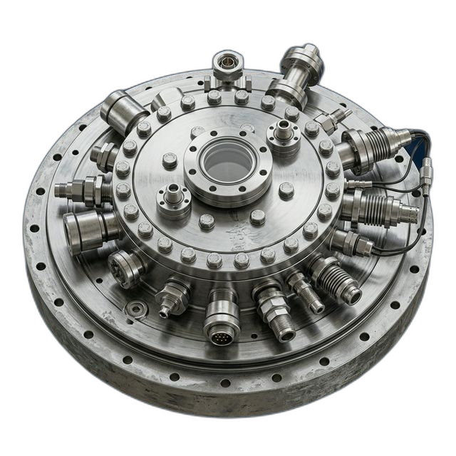
Vacuum Chamber Lid — 6061-T6 Aluminum for CVD Tool
A semiconductor equipment OEM building a new CVD (chemical vapor deposition) tool needed a chamber lid that seals against the chamber body under high vacuum at 10−6 Torr. Any surface defect on the O-ring sealing face causes a vacuum leak that contaminates the deposition process — every micro-scratch is a potential tool-down event.
The Challenge
The lid is 24″ diameter and 2.5″ thick — a large billet with significant material removal that causes residual stress warping. O-ring groove dimensions are ultra-critical: groove width ±0.001″, depth ±0.0005″, and surface finish ≤8 Ra in the groove. Flatness on the sealing face must hold within 0.001″ across the full 24″ diameter. Multiple gas injection ports and heater cartridge bores must not intersect the O-ring groove.
Our Approach
Started with stress-relieved billet. Roughed both sides to within 0.030″, then removed from the fixture for overnight stress normalization. Re-fixtured on a vacuum chuck to eliminate mechanical clamping distortion. Finished the sealing face and O-ring groove in a final pass with a carbide endmill at controlled chip load for ≤8 Ra. CMM-verified flatness at 24 points across the face.
The Result
Achieved 0.0007″ flatness across 24″ diameter — well within the 0.001″ spec. O-ring groove finish measured 6 Ra, beating the 8 Ra requirement. Both lids held 10−7 Torr base pressure on the first pump-down — no vacuum leak detected.
Why Vacuum Chamber Lids Demand Extreme Flatness
A vacuum chamber lid is deceptively simple — it’s a large aluminum disk that bolts onto the top of a process chamber. But in a CVD tool running at 10−6 Torr, the lid’s sealing face is the boundary between a controlled deposition environment and atmospheric contamination. The O-ring compressed between the lid and chamber body is the only barrier. If the sealing face has a scratch, a tool mark, or a flatness deviation that prevents uniform O-ring compression, the result is a virtual leak — atmospheric gases slowly permeate into the chamber, contaminating the thin-film deposition process and ruining device wafers.
The material choice is standard for vacuum applications: 6061-T6 aluminum. It offers good thermal conductivity (167 W/m·K) for heated lid configurations where the lid carries cartridge heaters to maintain the substrate at deposition temperature. It machines well, takes nickel plating for chemical resistance, and is lightweight enough that the lid can be handled by a single-person hoist rather than requiring a crane.
The Stress Management Problem
A 24″ diameter, 2.5″ thick billet of 6061-T6 contains enormous residual stress from the rolling and heat-treatment process. When you remove 60–70% of the material to create the lid’s features — gas ports, heater bores, O-ring groove, bolt circle, lifting holes — the stress balance shifts. The part warps. On a 24″ diameter part, even a few ten-thousandths of stress-induced bow can push the sealing face out of the 0.001″ flatness spec.
Most shops rough the part, finish it, and then discover it’s warped. They try to re-machine the sealing face flat, but re-clamping a warped part introduces new distortion. The result is a cycle of diminishing returns: each correction introduces new stress, and the part never truly converges to flat. The customer’s previous vendor had delivered lids that required multiple rework cycles and still showed marginal flatness.
How We Solved It
We designed the machining sequence around stress management from the start, not as an afterthought:
- Stress-relieved billet selection. We started with billet that had been stress-relieved after heat treatment. This doesn’t eliminate internal stress, but it reduces the magnitude significantly compared to standard mill plate. Less residual stress means less warping when material is removed.
- Symmetric roughing with overnight normalization. We roughed both sides of the lid to within 0.030″ of final dimensions — top and bottom — removing material symmetrically to keep the stress balanced. Then we unfixtured the part and let it sit overnight to allow the remaining residual stress to redistribute. When we re-measured in the morning, the part had moved 0.003″ — exactly the kind of warping that would have been locked into a finished part at a less careful shop.
- Vacuum chuck fixturing for finish passes. For the finish operations, we mounted the lid on a vacuum chuck instead of mechanical clamps. Mechanical clamps pull a thin part into conformance with the fixture — it measures flat while clamped, then springs back to its warped shape when released. A vacuum chuck applies uniform holding force across the entire bottom surface without introducing bending moments. What you measure on the machine is what you get off the machine.
- Controlled chip load for O-ring groove finish. The O-ring groove is the most critical feature on the entire part. We cut it in the final pass using a precision carbide endmill with a calculated chip load that produces a consistent surface texture without burnishing or smearing. Burnishing creates a smooth-looking surface but embeds subsurface damage that can flake off over time — releasing particles into the vacuum chamber. Our controlled cut produced a clean 6 Ra finish with no subsurface damage.
- 24-point CMM flatness verification. We verified the sealing face flatness using a CMM with 24 measurement points distributed across the full 24″ diameter. Not 4 points. Not 8. Twenty-four points to capture any localized high or low spots that a sparse measurement grid would miss. The flatness map shipped with the part so the customer could correlate any future leak issues to specific sealing zones.
Vacuum Performance Results
The customer installed both lids on their CVD chambers and ran pump-down qualification tests. Both lids reached 10−7 Torr base pressure on the first pump-down — an order of magnitude better than the 10−6 Torr operating requirement. No leak was detected with a helium leak detector at a sensitivity of 10−9 atm·cc/sec. The O-ring showed uniform compression marks around the full circumference, confirming that the sealing face flatness was providing consistent O-ring contact.
The customer noted that their previous vendor’s lids had required shimming at certain bolt positions to achieve acceptable vacuum. These lids required no shimming — bolts were torqued to spec and the chamber pumped down cleanly.
What the Customer Said
“We’ve struggled with lid flatness from every vendor we’ve tried. The stress-relief and vacuum chuck approach that RivCut used is the first time we’ve received lids that don’t need shimming. First pump-down to 10−7 Torr — that tells you everything about the sealing face quality.”
By the Numbers
Upload Your CAD File
Get instant AI pricing, a free DFM review, and full documentation on every order.
No minimums · 100% Made in USA · Never brokered · Ships anywhere in the US