Why Drawing Callouts Matter
A CNC machine shop reads your drawing before it reads your CAD file. The drawing tells the machinist what matters -- which dimensions are critical, what surface finish you need and what material to use. Without clear callouts, the shop has to guess. And guessing costs you time and money.
Good callouts do three things. They remove ambiguity. They set clear expectations. And they give the shop enough information to make your part right the first time.
The drawing is the legal document. If the part matches the drawing, the shop did its job. If the drawing is wrong, you pay for the mistake -- not the shop.
Need help with your drawing callouts?
Upload your CAD file and get a free DFM review, we'll flag tolerance issues, missing callouts and manufacturability concerns before you cut metal.
Upload CAD for Free DFM ReviewTitle Block Basics
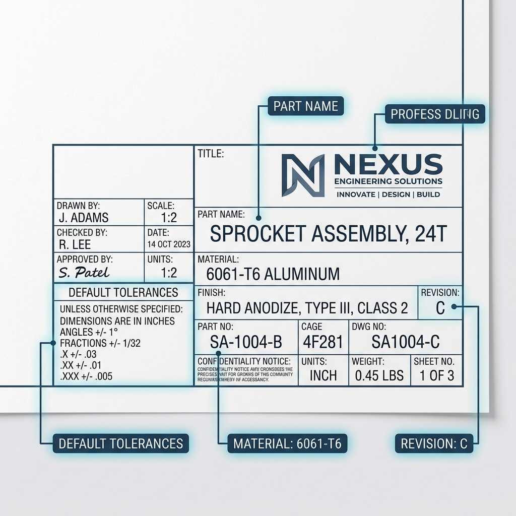
Every drawing needs a title block. This is the box in the lower right corner that contains the most important information about your part. The machinist reads this first.
| Title Block Field | What to Include | Why It Matters |
|---|---|---|
| Part Name | Descriptive name (e.g., "Motor Mount Bracket") | Identifies the part on the shop floor |
| Part Number | Your internal PN (e.g., "MMB-2026-001") | Tracks revisions and purchase orders |
| Material | Full spec (e.g., "6061-T6 Aluminum per AMS-QQ-A-250/11") | Tells the shop what to order |
| Units | Inches or millimeters | Prevents unit mix-ups (a common cause of scrap) |
| Scale | Drawing scale (e.g., 2:1, 1:1, 1:2) | Lets the machinist judge proportions visually |
| Default Tolerances | General tolerances for undimensioned features | Covers every dimension not explicitly toleranced |
| Revision | Rev letter and date (e.g., "Rev C - 03/13/2026") | Ensures the shop uses the latest version |
| Surface Finish | Default finish (e.g., "125 Ra unless noted") | Sets the baseline for all surfaces |
Set a default tolerance in the title block (e.g., +/-0.005" for 2-place decimals, +/-0.010" for 1-place). Then you only need to call out tolerances on the features that require something tighter. This keeps your drawing clean and easy to read.
Dimension Callouts
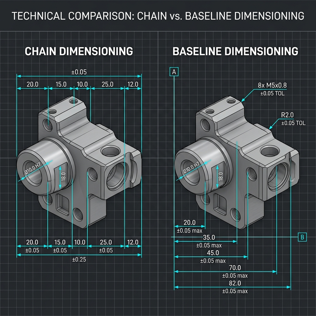
Dimensions tell the machinist the size and location of every feature. There are two main ways to dimension a part: chain dimensioning and baseline dimensioning.
Chain vs. Baseline Dimensioning
Chain dimensioning measures each feature from the previous one. Feature B is 1.000" from A. Feature C is 1.000" from B. The problem is that tolerances add up. If each dimension has +/-0.005", the distance from A to C has +/-0.010" of tolerance stack-up.
Baseline dimensioning measures every feature from the same reference point (datum). Feature B is 1.000" from datum A. Feature C is 2.000" from datum A. No stack-up. Each feature has its own independent tolerance.
Chain dimensioning is the number one cause of stack-up problems on CNC parts. Use baseline dimensioning from datums for any part with three or more features in a line.
Tolerance Types
| Tolerance Type | Example | When to Use |
|---|---|---|
| Bilateral (equal) | 1.000 +/-0.005" | General features, most dimensions |
| Bilateral (unequal) | 1.000 +0.003/-0.001" | When drift in one direction is more acceptable |
| Unilateral | 1.000 +0.000/-0.010" | Press-fit holes, interference fits |
| Limit dimensions | 0.995 / 1.005 | Fits and clearances where both limits matter |
For most CNC parts, bilateral tolerances work best. They let the machinist aim for the middle of the range. Use unilateral tolerances only when the part must not go above or below a specific size -- like a shaft that must fit into a bearing.
Surface Finish Symbols
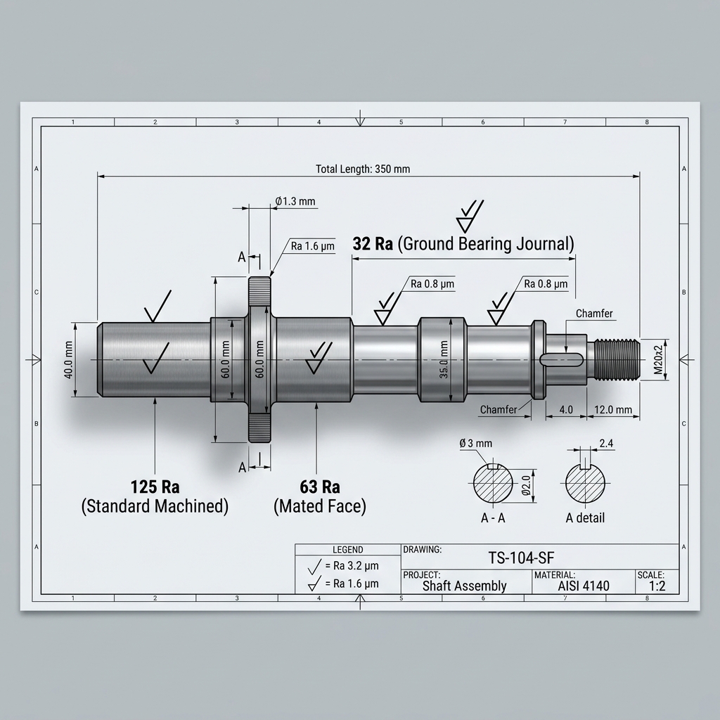
Surface finish tells the shop how smooth a surface needs to be. It is measured in Ra (roughness average) in microinches or micrometers. A lower number means a smoother surface.
The surface finish symbol looks like a check mark with the Ra value written next to it. You place it on the surface that needs a specific finish. Surfaces without a symbol get the default finish from the title block.
| Ra (Microinches) | Ra (Micrometers) | Typical Process | Common Use |
|---|---|---|---|
| 250 | 6.3 | Rough machining, sawing | Non-functional surfaces |
| 125 | 3.2 | Standard CNC milling | General machined surfaces |
| 63 | 1.6 | Fine CNC milling/turning | Mating surfaces, visible faces |
| 32 | 0.8 | Grinding | Bearing journals, sealing surfaces |
| 16 | 0.4 | Lapping, honing | Hydraulic seals, optical flats |
| 8 | 0.2 | Superfinishing, polishing | Precision instruments, mirrors |
Most CNC milled parts come off the machine between 63 and 125 Ra. You do not need to call out a surface finish in that range -- it happens naturally. Only add surface finish callouts for surfaces that need to be smoother than standard.
Going from 125 Ra to 63 Ra adds little cost. Going from 63 Ra to 32 Ra often requires grinding -- a separate operation that adds time and money. Going below 16 Ra can double the part cost. Only specify tight finishes where function demands it, like sealing faces and bearing surfaces.
Get your parts made right the first time
Upload your drawing. Get instant pricing. Ships in as few as 3 days.
Get an Instant QuoteMaterial Callouts
Your material callout tells the shop exactly what to buy. A vague callout like "aluminum" is not enough. There are dozens of aluminum alloys and each machines differently and has different properties.
What a Good Material Callout Includes
- Alloy and temper: 6061-T6, 7075-T651, 304 stainless steel, Ti-6Al-4V
- Material specification: AMS-QQ-A-250/11, ASTM A276, AMS 4928
- Form: Bar, plate, sheet, casting (affects grain direction and properties)
- Heat treatment: If needed after machining (e.g., "Heat treat to HRC 58-62 per AMS 2759")
- Finish or coating: Anodize Type II, hard anodize Type III, nickel plate, passivate
| Material | Correct Callout | Common Application |
|---|---|---|
| Aluminum 6061 | 6061-T6 per AMS-QQ-A-250/11 | General purpose brackets, housings |
| Aluminum 7075 | 7075-T651 per AMS-QQ-A-250/12 | Aerospace structural parts |
| 303 Stainless | 303 SS per ASTM A582 | Free-machining fittings, shafts |
| 304 Stainless | 304 SS per ASTM A276 | Corrosion-resistant components |
| 316 Stainless | 316L SS per ASTM A276 | Medical, marine, chemical processing |
| 4140 Steel | 4140 per ASTM A29, HT to HRC 28-32 | Gears, shafts, high-strength parts |
| Titanium Grade 5 | Ti-6Al-4V per AMS 4928 | Aerospace, medical implants |
The material hardness directly affects how tight a tolerance the shop can hold. Harder materials cause more tool wear and may need slower feeds, which increases cost. Call out the material early so the shop can quote accurately.
Thread Callouts
Thread callouts tell the shop the size, pitch, class and depth of threaded features. A complete thread callout prevents the shop from guessing -- and prevents you from getting the wrong thread.
Unified Thread Callouts (Inch)
The format is: Size - Threads Per Inch - Series - Class - Internal/External
- 1/4-20 UNC-2B: 1/4" diameter, 20 threads per inch, coarse series, class 2, internal (tapped hole)
- 1/4-20 UNC-2A: Same thread, but external (on a shaft or bolt)
- 10-32 UNF-3B: #10, 32 TPI, fine series, class 3 (tighter fit), internal
Metric Thread Callouts
The format is: M + Diameter x Pitch
- M6x1.0: 6mm diameter, 1.0mm pitch (coarse)
- M6x0.75: 6mm diameter, 0.75mm pitch (fine)
- M8x1.25-6H: 8mm, 1.25mm pitch, tolerance class 6H (internal)
| Thread Detail | What to Specify | Example |
|---|---|---|
| Size and pitch | Diameter and TPI or mm pitch | 1/4-20 UNC or M6x1.0 |
| Class/tolerance | Fit class (1=loose, 2=general, 3=tight) | 2B (internal) or 2A (external) |
| Depth | Thread depth and drill depth | "1/4-20 UNC-2B x 0.500 DP, drill thru" |
| Countersink | Chamfer at hole entry | "CSK 0.030 x 45 deg" |
| Thread direction | Only if left-hand | "1/4-20 UNC-2B LH" (left-hand) |
A missing thread depth is one of the most common drawing errors. For blind holes, specify both the thread depth and the drill depth separately. The drill must go deeper than the thread to allow full thread engagement. A good rule: drill depth = thread depth + 2 pitches.
GD&T Symbols
Geometric Dimensioning and Tolerancing (GD&T) controls the shape, orientation and location of features -- things that regular dimensions cannot control. You do not need GD&T on every drawing. But for parts that assemble together, GD&T makes your intent crystal clear. Keep our GD&T reference guide handy for symbol definitions.
Most Common GD&T Symbols
| Symbol | Name | What It Controls | When to Use |
|---|---|---|---|
| ◯ | Position | Location of a feature relative to datums | Bolt hole patterns, pin locations |
| ▬ | Flatness | How flat a surface is | Mating surfaces, sealing faces |
| ▭ | Straightness | How straight a line or axis is | Shafts, rails, edges |
| ⊥ | Perpendicularity | 90-degree relationship between surfaces | Walls relative to a base |
| ∥ | Parallelism | Parallel relationship between surfaces | Top and bottom faces of a plate |
| ○ | Circularity | How round a cross-section is | Bearing bores, O-ring grooves |
| ⌀ | Cylindricity | Roundness along the entire length | Precision shafts, pistons |
| ❏ | Concentricity | Two features share the same center axis | Stepped shafts, nested bores |
A GD&T callout goes inside a feature control frame. This is a box with compartments that read left to right: the geometric symbol, the tolerance value and the datum references.
For example, a position callout on a hole pattern might say: "Position within 0.010" diameter at MMC, referenced to datums A, B and C." This tells the shop exactly where each hole must be, how much it can move and what surfaces to measure from.
You do not need to GD&T every feature. Start with flatness on mating surfaces and position on hole patterns. These two callouts solve 80% of assembly problems. As you get comfortable, add perpendicularity and parallelism where needed. See our tolerances for engineers guide for practical GD&T values.
Common Drawing Mistakes
We review hundreds of drawings every month. These are the mistakes we see most often -- and how to fix them.
- Missing tolerances on critical dimensions. If a dimension does not have a tolerance, the shop uses the default from the title block. If the default is +/-0.010" but you need +/-0.002", you will get the wrong part. Always tolerance critical features explicitly.
- Over-tolerancing everything. The opposite problem. When every dimension says +/-0.001", nothing is actually critical. The shop has to treat every feature as precision, which drives up cost. Only tighten what matters. Learn what realistic tolerances your shop can actually hold.
- No material specification. "Aluminum" is not a material spec. "6061-T6 per AMS-QQ-A-250/11" is. Without a proper spec, the shop cannot order the right material or provide a material certificate.
- Missing thread depth. Specifying "1/4-20 tapped hole" without a depth leaves the machinist guessing. Always call out thread depth and drill depth separately for blind holes.
- Chain dimensioning. Measuring each feature from the previous one creates tolerance stack-up. Use baseline dimensioning from datums.
- No revision control. Sending a drawing without a revision letter means the shop cannot confirm they have the latest version. Always include a rev letter and date.
- Conflicting dimensions. When the front view shows 1.000" but the section view shows 0.995", the shop has to stop and ask which is correct. That delay costs you lead time.
- No edge break callout. Sharp edges from machining can cut fingers and cause stress concentrations. Add a general note like "Break all sharp edges 0.005 to 0.015 unless noted."
A clean drawing with clear callouts gets quoted faster, manufactured faster and inspected faster. Ambiguity is the enemy of speed. Our DFM review team catches these issues before machining starts.
Drawing Callouts Cheat Sheet
Get a one-page PDF with all the callout symbols, tolerance formats and surface finish specs, keep it at your desk.
No spam, ever. We respect your privacy.
Frequently Asked Questions
What are engineering drawing callouts?
Engineering drawing callouts are annotations on a technical drawing that tell the machine shop how to make the part. They include dimensions, tolerances, surface finish requirements, material specifications, thread callouts and GD&T symbols. They are the communication bridge between the designer and the machinist.
What surface finish should I specify for CNC parts?
Most CNC milled parts come off the machine at 63 to 125 Ra microinches. That is fine for most surfaces. Specify 32 Ra for ground surfaces like bearing journals. Only go to 16 Ra or below for sealing faces and precision instruments -- it requires secondary operations and costs significantly more.
How do I call out threads on a drawing?
Use the standard format: size, threads per inch, series and class. For inch threads: "1/4-20 UNC-2B" (internal) or "1/4-20 UNC-2A" (external). For metric: "M6x1.0." Always include thread depth for blind holes and specify the drill depth separately.
What is the difference between unilateral and bilateral tolerances?
Bilateral tolerances allow variation in both directions, like 1.000 +/-0.005". Unilateral tolerances only go one way, like 1.000 +0.000/-0.010". Use bilateral for most features. Use unilateral for press fits and interference fits where the part must not exceed a specific size.
What are the most common drawing callout mistakes?
Missing tolerances on critical dimensions, over-tolerancing non-critical features, vague material callouts, missing thread depth, chain dimensioning instead of baseline dimensioning and no revision control. Each one causes delays, rework, or scrapped parts.