By the RivCut Engineering Team. Learn more about RivCut.
Anodizing protects aluminum parts from wear. It stops rust. It also adds clean color to raw metal. However, anodizing changes the actual size of your parts. If you do not plan for this, your screws may not fit. Your bearings may jam.
Here is the quick rule: Anodizing grows the outside size of your parts. At the same time, it shrinks the inside size of your holes. The coating builds up on the surface. It also penetrates into the metal. This guide shows you how to adjust your CAD dimensions. Then your parts will fit perfectly after anodizing.
The 50/50 Rule: Buildup vs. Penetration
Anodizing is not like paint. It does not just sit on top of the metal. It uses an acid bath and electricity. This converts raw aluminum. The process turns the surface metal into a hard aluminum oxide layer.
As this oxide layer grows, half of it penetrates into the raw aluminum. The other half builds up on the surface. This is called the 50/50 rule.
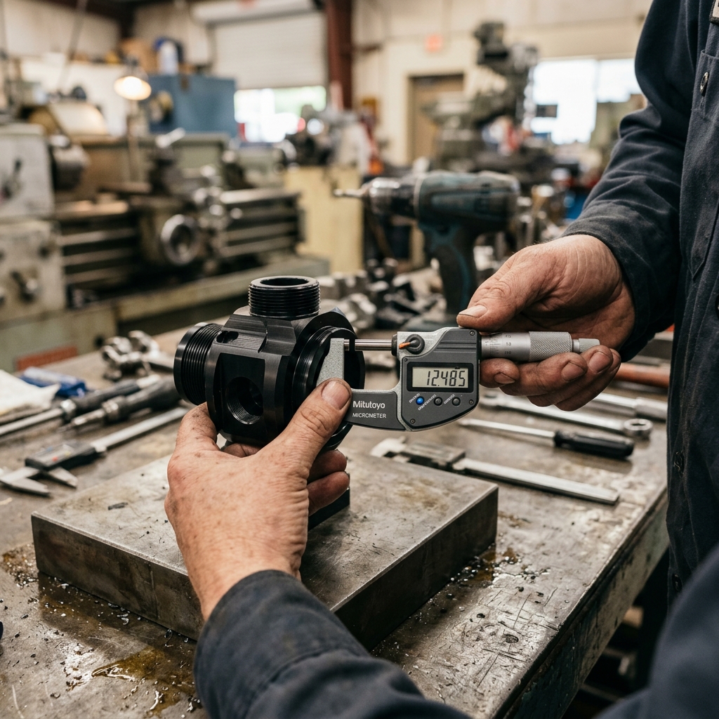
This buildup is what changes your part dimensions. Let us look at a standard coating. If the total coating is 0.001 inches thick, the surface of your part grows. It will grow by 0.0005 inches per side.
How Coating Type Affects Dimensional Changes
The thickness of the anodize layer depends on the type you choose. Here is how Type II and Type III (Hard Coat) compare:
| Anodize Type | Standard Total Thickness | Buildup per Surface (50%) | Shaft Diameter Change | Hole Diameter Change |
|---|---|---|---|---|
| Type II (Decorative) | 0.0008 inches (0.8 mils) | 0.0004 inches | Grows by +0.0008 inches | Shrinks by -0.0008 inches |
| Type III (Hard Coat) | 0.0020 inches (2.0 mils) | 0.0010 inches | Grows by +0.0020 inches | Shrinks by -0.0020 inches |
Shafts vs. Holes: Dimensional Math
Anodizing affects outside dimensions differently than inside dimensions. You must calculate the change per side. This is very important for shafts and holes.
Outside Dimensions (Shafts and Blocks)
The thickness builds up on both sides of a shaft.
- The rule: The total diameter increases by 2 times the buildup value.
- The formula: Post-plating shaft diameter = Pre-plating diameter + (2 * Buildup)
- Example: You have a shaft. You choose Type II anodizing. The buildup is 0.0004 inches. A 1.0000-inch shaft will measure 1.0008 inches after plating.
Inside Dimensions (Holes and Slots)
The coating builds up on the inner walls. This makes the opening smaller.
- The rule: The total hole diameter decreases by 2 times the buildup value.
- The formula: Post-plating hole diameter = Pre-plating diameter - (2 * Buildup)
- Example: You have a hole. You choose Type II anodizing. The buildup is 0.0004 inches. A 0.5000-inch hole will measure 0.4992 inches after plating.
Type II Anodizing (Decorative)
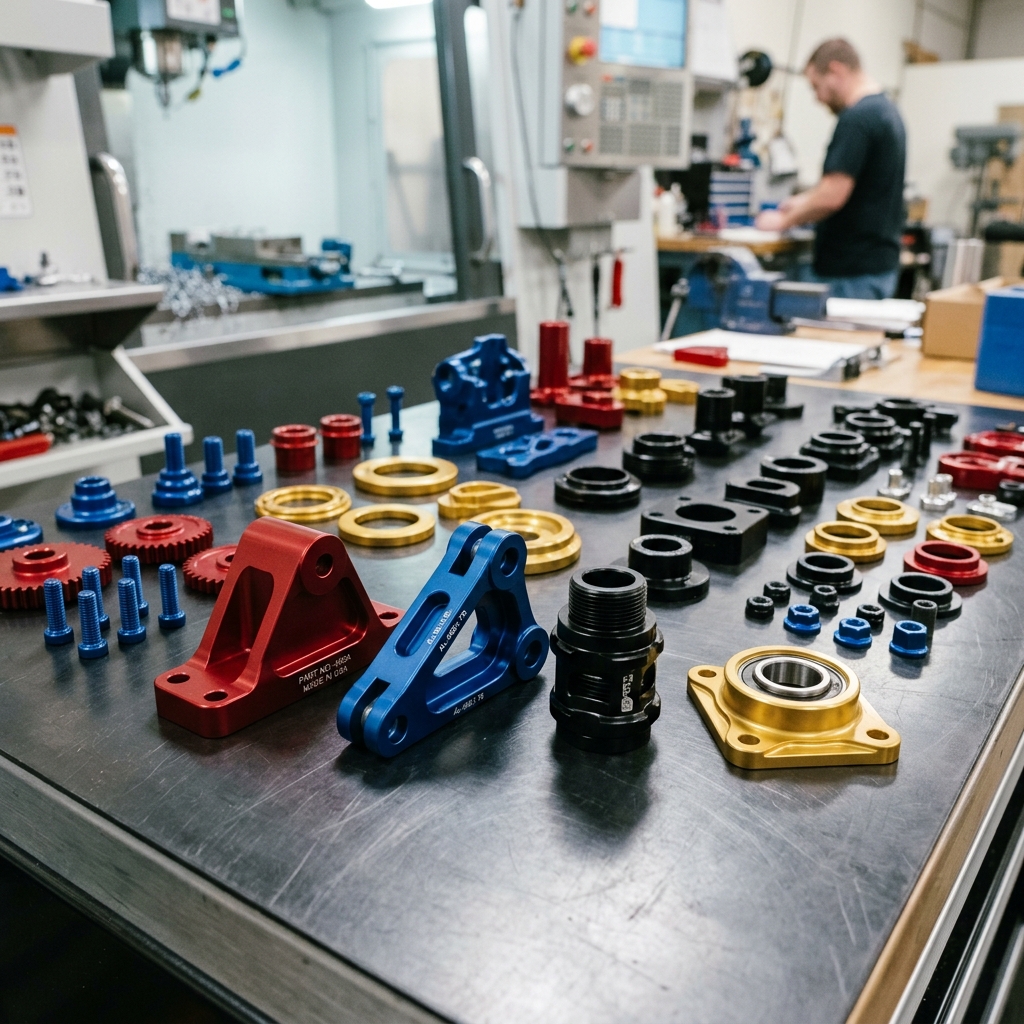
Type II anodizing is the most common finish. It is used for color. It also adds mild protection. It is a thin coating.
The typical thickness of a Type II coating is thin. It is between 0.0002 and 0.0008 inches per side.
This thin layer has a small effect on parts. For most general parts, the change is very small. You can ignore it. A standard loose fit will still work fine.
But high-precision press fits are different. For these, you must make adjustments. You should cut your bores slightly larger. This allows for the 0.0004-inch buildup on each wall.
Type III Anodizing (Hard Coat)
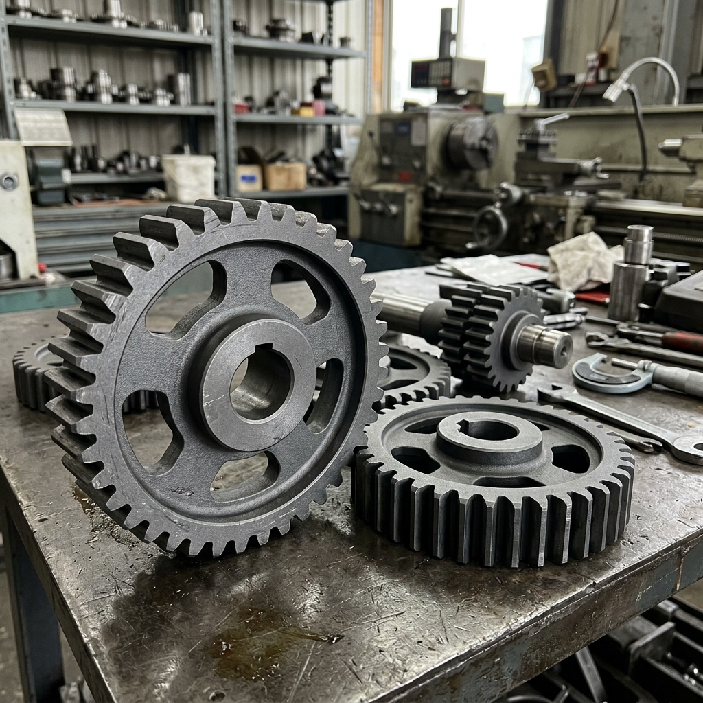
Type III anodizing is also called hard coat. It is much thicker. It is also harder. It is used for parts that face heavy wear. It is great for sliding friction.
The typical thickness of Type III hard coat is 0.0020 inches per side.
Because this coating is thicker, it has a big effect on dimensions. The buildup per surface is 0.0010 inches.
A 1.000-inch shaft grows to 1.002 inches. A 1.000-inch hole shrinks to 0.998 inches. This is a total change of 0.004 inches on a matching fit.
If you do not plan for this change, your parts will not fit. You must machine your raw parts with this shift in mind.
Sizing Threaded Holes for Anodizing
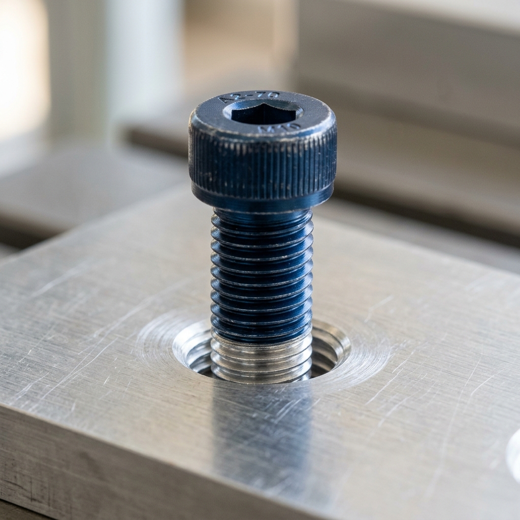
Threaded holes are very sensitive to anodizing. The coating grows on both sides of the thread V-shape. This makes the thread pitch diameter change. The change is 4 times the buildup value.
Sizing Threads for Type II Anodizing
For standard Type II coatings, standard taps are usually fine. The thin coating will not cause the bolt to bind.
Sizing Threads for Type III Hard Coat
For Type III hard coat, the heavy buildup will cause standard threads to bind. You have two options to fix this:
- Mask the threads: Use plastic plugs. This keeps the acid out of the hole. The threads will stay raw aluminum.
- Use oversize taps: Cut the threads slightly larger before anodizing. These are called GH taps. They leave extra room for the coating buildup.
DFM Guidelines: Designing for Anodizing
To prevent assembly failures, follow these simple DFM guidelines:
1. Masking Critical Features
Masking uses liquid paint or plugs. This protects critical surfaces from the anodizing bath.
Use masking on:
- High-precision bearing bores.
- Electrical grounding points. (Anodize is an electrical insulator.)
- Sliding surfaces with tight clearances.
- Tiny threaded holes.
Keep in mind that masking adds manual labor. This will increase the cost of your parts.
2. Sizing Bores for Press Fits
If you have a bearing that needs a tight press fit, anodizing will change the fit.
You should machine the hole slightly larger. Or you can mask the bore. For example, you need a 0.5000-inch final bore. You choose Type II anodizing. Machine the raw hole to 0.5008 inches. The coating buildup will bring it back to 0.5000 inches.
3. Specify Pre-Plating vs. Post-Plating Dimensions
Tell your machine shop if your drawing tolerances apply before or after plating.
- Post-plating: This is the default for most drawings. The shop will adjust their machining sizes to account for the anodizing buildup.
- Pre-plating: The machinist cuts the metal exactly to the drawing sizes. The anodizing then changes the final size.
Frequently Asked Questions
Does anodizing make parts bigger or smaller?
Both. Anodizing grows outside dimensions (shafts and blocks) and shrinks inside dimensions (holes and slots). On a diameter, the change equals about twice the per-surface buildup, so a shaft and a hole of the same nominal size move in opposite directions by the same amount.
How much does Type II anodizing add to a dimension?
A typical Type II coating is about 0.0008 inches (0.8 mils) total. That adds roughly +0.0008 inches to a shaft diameter and removes about -0.0008 inches from a hole diameter. Type III hard coat is thicker (around 0.0020 inches), so the dimensional shift is larger.
Should I machine to pre-plating or post-plating dimensions?
Tell your shop which your drawing tolerances refer to. If the callout is post-plating (final size after anodizing), the machinist cuts shafts slightly small and holes slightly large to leave room for the coating. If it's pre-plating, they machine to the drawing and the coating changes the final size.
Do threaded holes need to be oversized for anodizing?
For Type II, standard taps are usually fine. For Type III hard coat, the heavier buildup can bind threads, so use oversize (GH) taps or mask the threads to keep them within spec.
Is anodized aluminum conductive?
No. Aluminum oxide is an electrical insulator. If you need a point for a grounding wire, you must mask that area so it remains raw aluminum.
Sources & References
- MIL-PRF-8625F, Anodic Coatings for Aluminum and Aluminum Alloys (defines Type II sulfuric and Type III hard anodize, including standard coating thickness ranges).
- Aluminum Anodizers Council, process fundamentals and dimensional buildup/penetration guidance. Aluminum Anodizers Council