Why Parts Distort from Clamping
Every clamp applies force. That force bends the part, even if only a little. If the force stays within the elastic range, the part springs back when you release. No harm done.
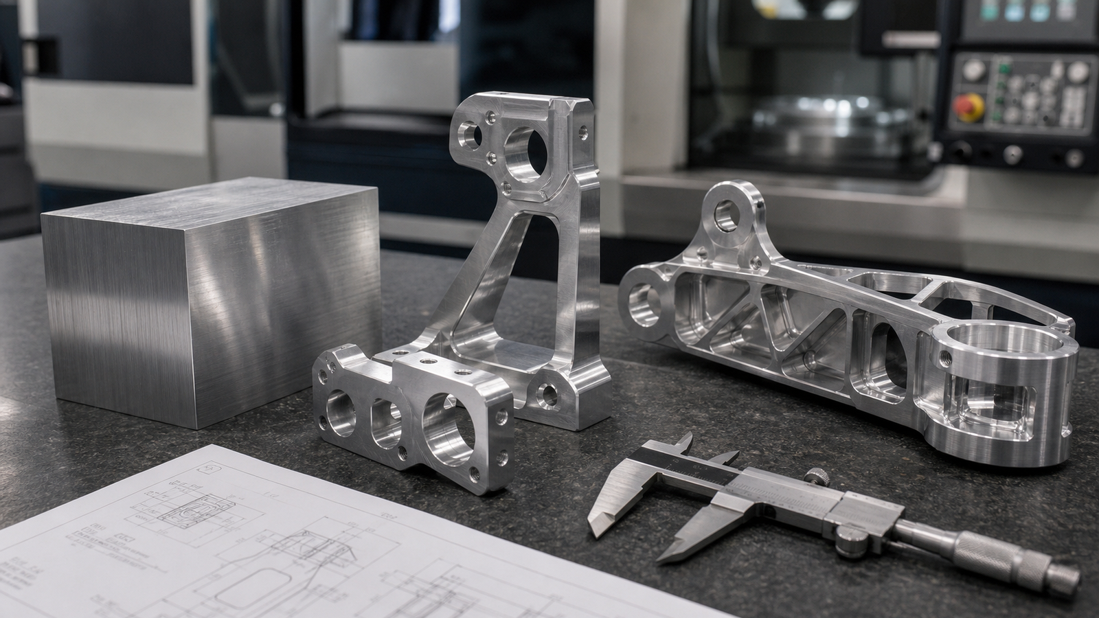
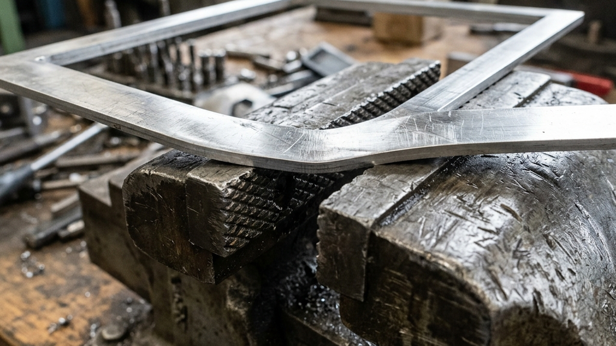
The problem starts when you machine the part while it is bent. You remove material from a stressed shape. When the clamp releases, the part relaxes into a new shape. That new shape is wrong.
Thin walls, hollow sections and soft materials are the most at risk. A solid steel block can handle huge clamp force. A thin aluminum bracket cannot.
If your part moves when you release the clamp, you clamped too hard or in the wrong spot.
Clamping Force vs. Deformation
How much force causes distortion? It depends on the part shape, material and wall thickness. Here are some general guidelines.
| Wall Thickness | Aluminum 6061 | Steel 4140 | Titanium Ti-6Al-4V |
|---|---|---|---|
| 0.250 in (6.35 mm) | Safe up to 500 lbs | Safe up to 1,200 lbs | Safe up to 800 lbs |
| 0.125 in (3.18 mm) | Safe up to 150 lbs | Safe up to 400 lbs | Safe up to 250 lbs |
| 0.060 in (1.52 mm) | Max 30 - 50 lbs | Max 100 - 150 lbs | Max 60 - 80 lbs |
| 0.030 in (0.76 mm) | Max 10 - 15 lbs | Max 30 - 50 lbs | Max 15 - 25 lbs |
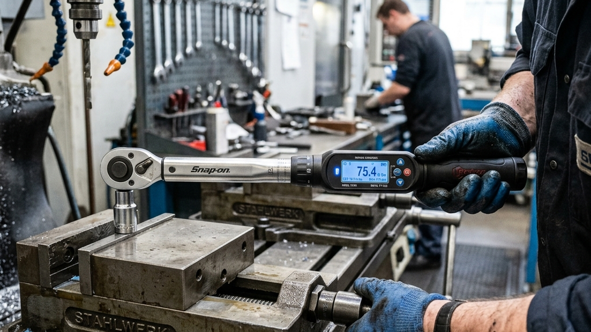
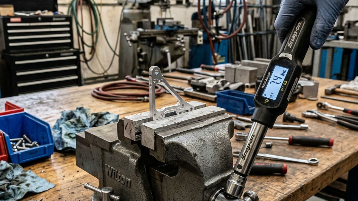
Most operators over-clamp because they are afraid the part will move during cutting. Use a torque wrench instead of guessing. Start at 50% of your normal torque and increase only if the part moves.
Thin-Wall Machining Strategies
Thin walls need special treatment. You cannot just clamp harder and hope for the best. Here are proven strategies.
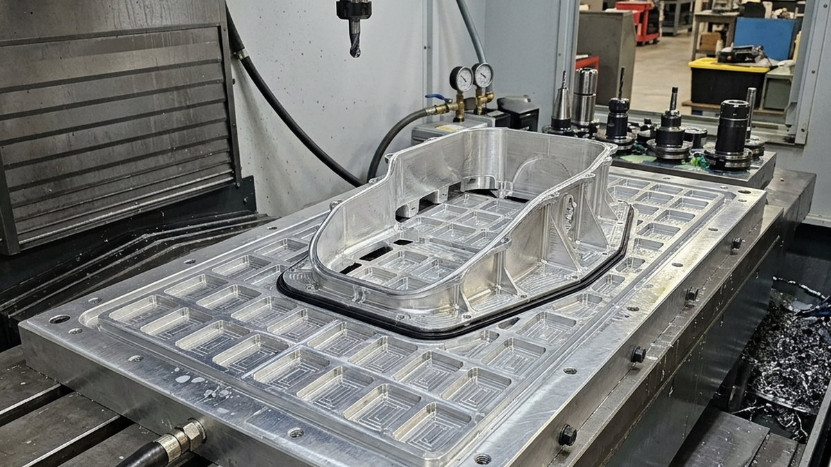
Support the Walls
Fill hollow sections with support material before clamping. This gives the clamp something to push against besides thin walls.
- Wax fill, Melt low-temperature wax into cavities. It supports walls during machining. Remove with heat after.
- Machinable foam, Press rigid foam into pockets. It absorbs clamp force without deforming the part.
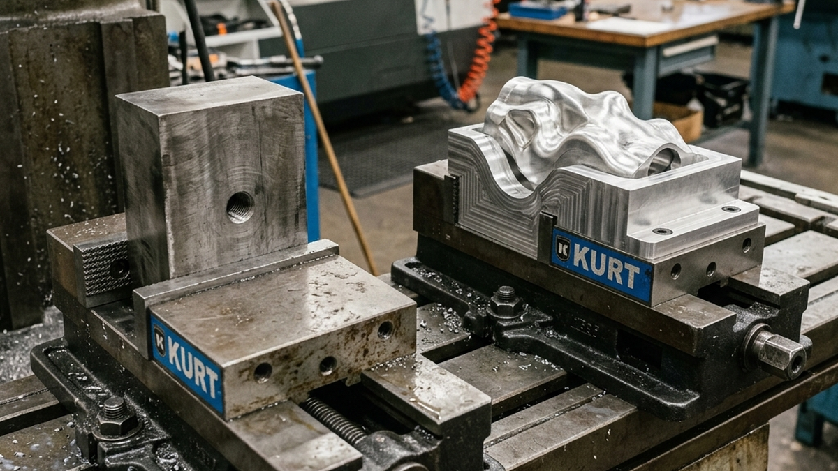
- Custom soft jaws, Machine soft jaws to match the part profile. The jaws cradle the part and spread force across a large area.
Reduce Cutting Forces
Less cutting force means less clamp force needed. Light cuts keep everything stable.
- Use smaller depths of cut (0.010 - 0.020 in)
- Increase spindle speed and reduce chip load
- Use sharp, coated end mills with high rake angles
- Climb mill to push the part into the fixture, not away from it
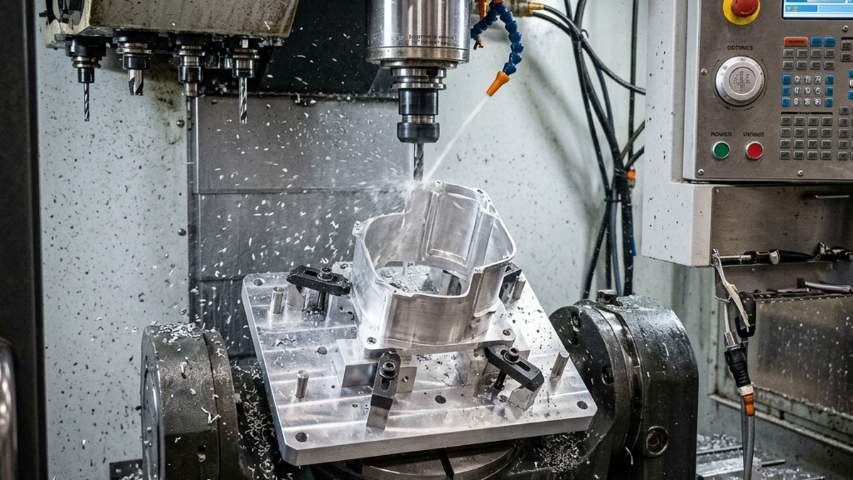
Machine in Stages
Do not remove all the material in one operation. Leave extra stock as support. Come back for a finish pass after roughing.
- Rough one side. Leave 0.020 in of stock on thin walls.
- Flip and rough the other side.
- Stress relieve if needed (heat treat or rest).
- Finish both sides with light cuts and low clamp force.
The Right Clamping Sequence
How you tighten matters as much as how much you tighten. A bad sequence creates uneven stress across the part.
Clamp the thickest, most rigid section first. Then move to thinner areas. Tighten all clamps to 50% first. Then go back and bring each clamp to full torque. This spreads force evenly.
For parts with multiple clamp points, follow this pattern:
- Center clamp first. This anchors the part in the middle.
- Then opposite corners. Like tightening lug nuts on a wheel.
- Half torque, then full. Never go to full torque on the first pass.
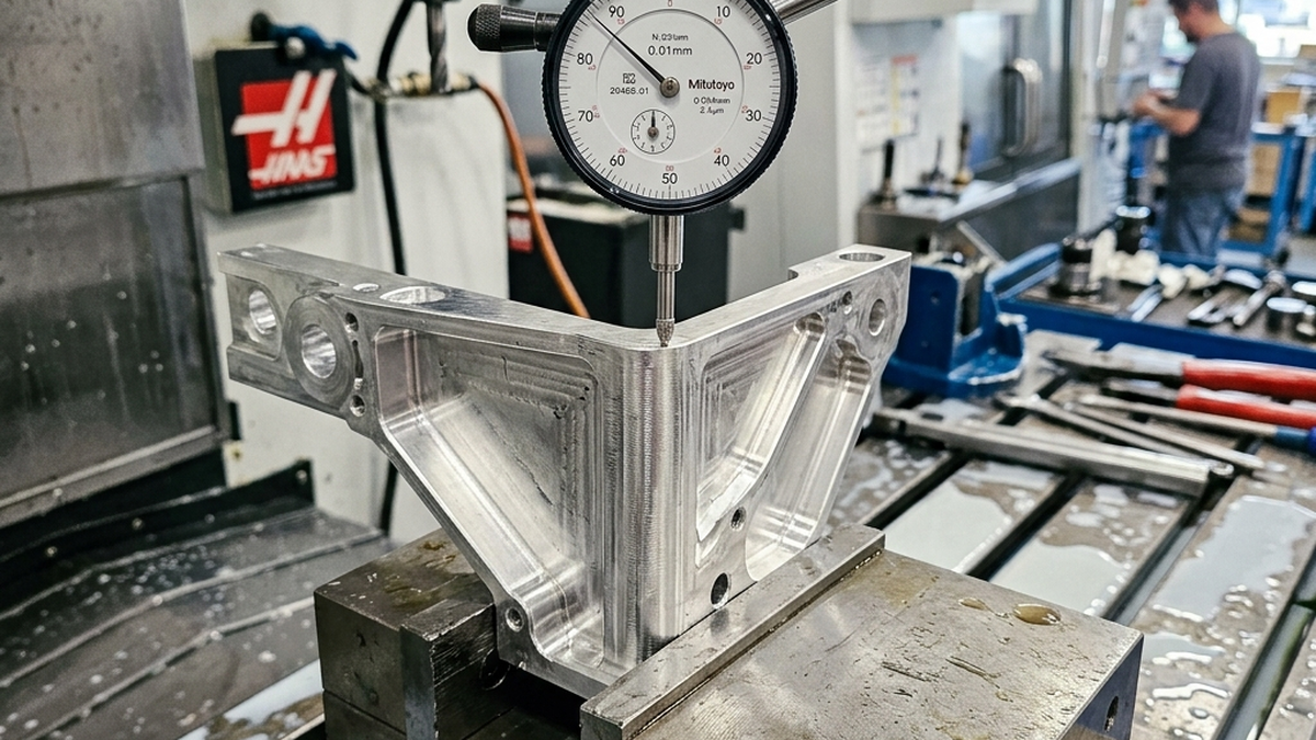
- Check with indicator. Touch off the part surface after clamping. If it moved more than 0.001 in, re-clamp with less force.
Stress Relief Between Operations
Raw material carries internal stress from rolling, forging, or extrusion. When you remove material, those stresses redistribute. The part warps.
Stress relief helps. It lets the material relax before you make the final cuts.
- Thermal stress relief, Heat aluminum to 350-400 F for 2-4 hours. Cool slowly. This releases most internal stress.
- Natural aging, Rough the part. Let it sit for 24-48 hours. Then measure and finish. Time alone lets some stress relax.
- Vibration stress relief, Vibrate the part at its resonant frequency. Faster than heat treatment. Works well on large parts.
Alternative Workholding Methods
Sometimes the best solution is to avoid mechanical clamping entirely. Other methods hold parts without point-loading.
- Vacuum fixturing, Distributes force across the entire bottom surface. No localized stress points. Great for flat, thin parts.
- Adhesive fixturing, Glue the part to a fixture plate with double-sided tape or UV-cure adhesive. Zero clamp distortion.
- Freeze fixturing, Freeze the part to a plate with a thin layer of water. The ice holds the part with zero stress. Remove with gentle heat.
- Magnetic chucks, For ferrous materials. Even force distribution. No clamps touching the part.
Struggling with part distortion? Send us your CAD file and we will recommend the best workholding approach for your geometry.