A Journey from Digital to Physical
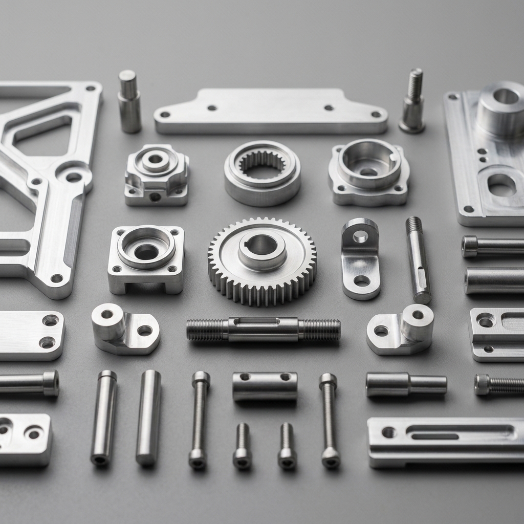
Have you ever held a perfectly shiny, incredibly smooth, complex piece of metal in your hand and wondered exactly how it was made? Translating an idea from a computer screen into a real-world, highly functional piece of metal requires a surprisingly intricate journey. In the world of CNC manufacturing, a design undergoes a fascinating series of transformations. Each phase relies on a mix of advanced digital software computation and traditional, heavy-duty mechanical engineering. By understanding this start-to-finish process, you can better appreciate the craftsmanship involved in modern manufacturing.
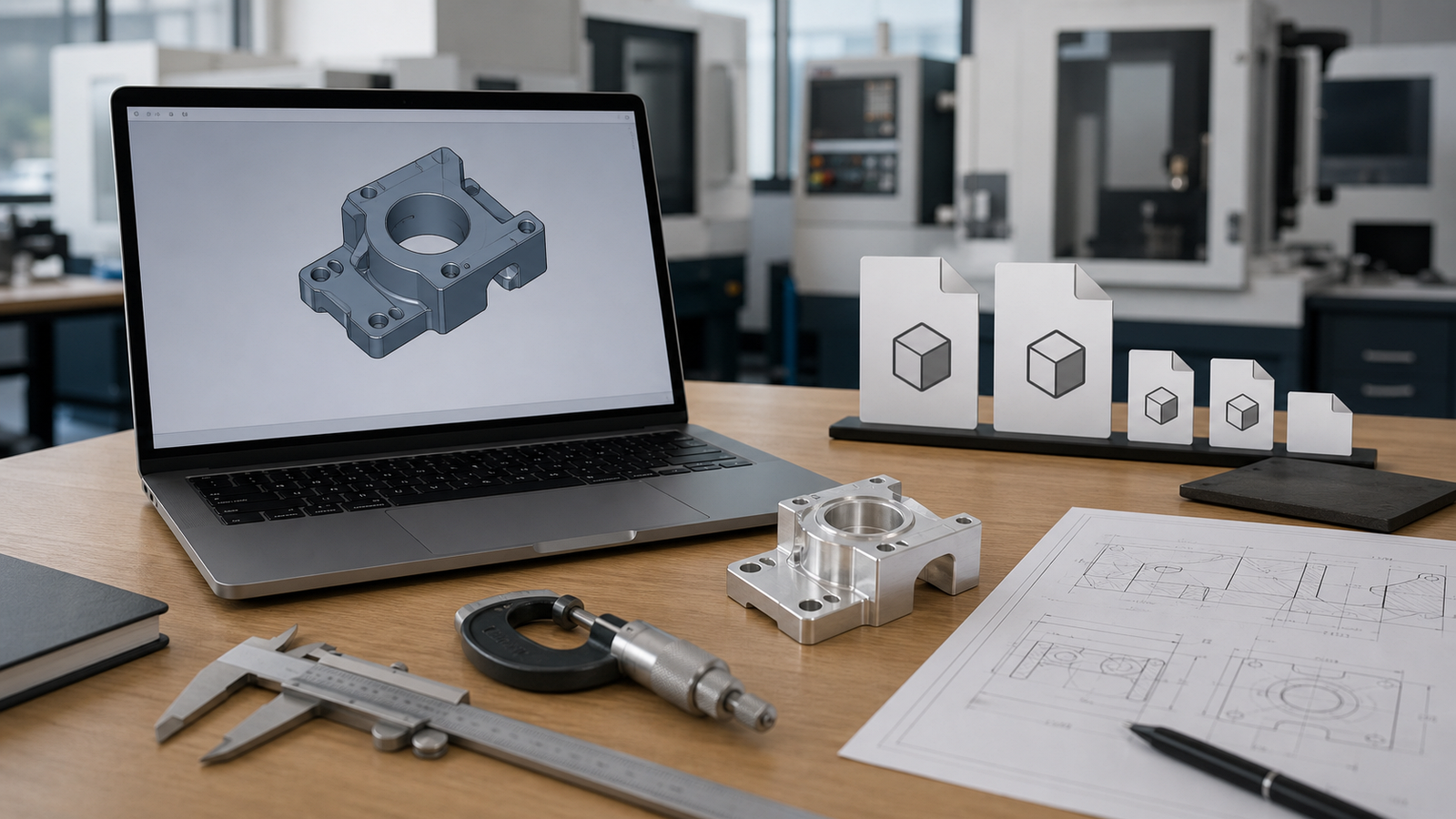
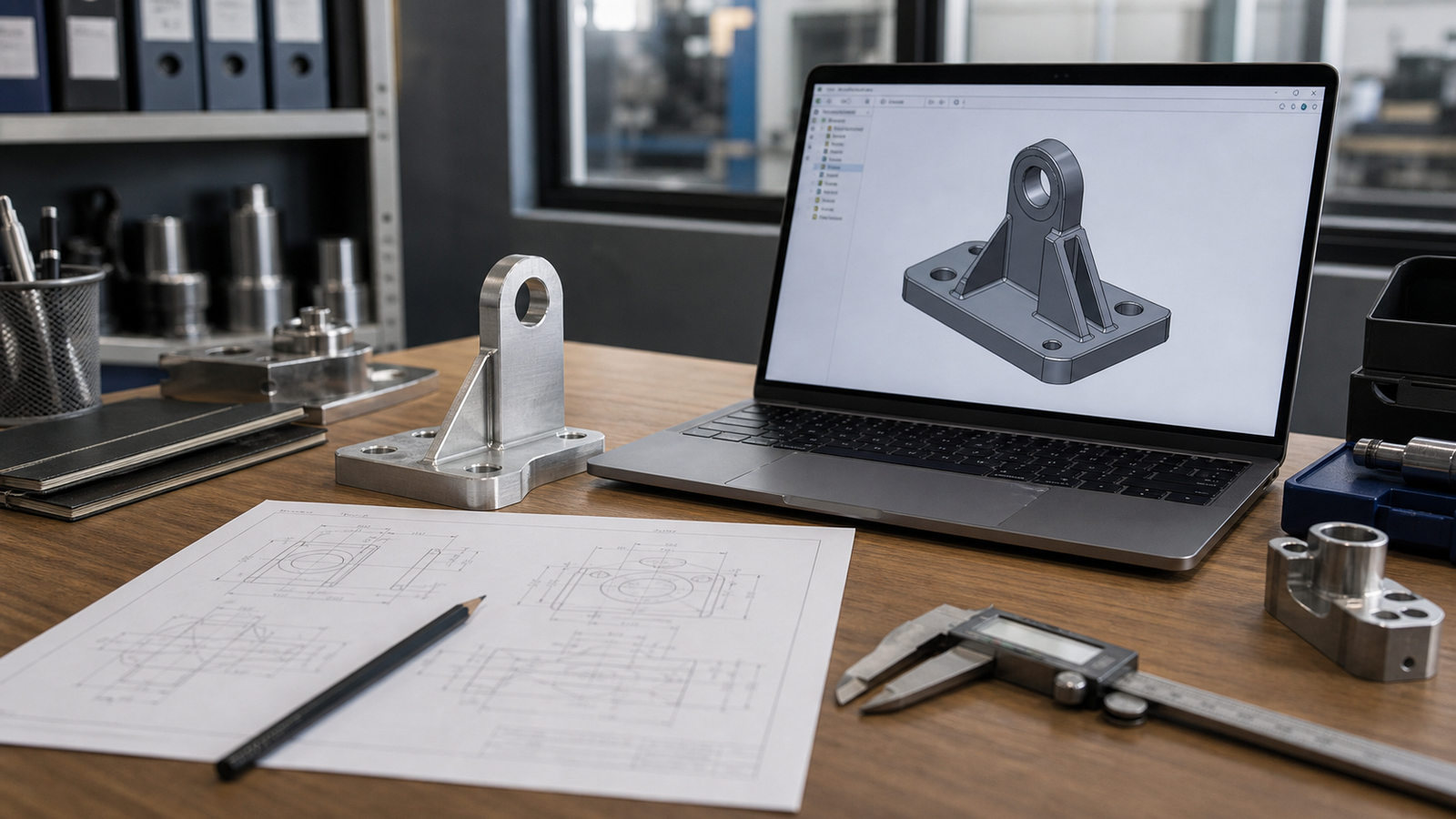
Step 1: The Design Phase (CAD)
Everything starts in the digital realm. Using advanced software systems like SolidWorks, AutoCAD, or Fusion 360, a designer creates a 3D model of the part. This step, known as Computer-Aided Design (CAD), is the blueprint for the entire project. The engineer meticulously maps out the dimensions, the thickness of the walls, the sizes of the holes and the sweeping curves of the surface.
However, a good CAD model is not just a pretty picture; it must be designed for manufacturability. The designer has to actively remember that the physical cutting tools are round, spinning cylinders. Therefore, they must avoid drawing perfectly sharp internal corners that a round tool cannot possibly cut. They must also ensure holes are not so incredibly deep that standard drill bits cannot reach the bottom. A strong CAD design makes the rest of the manufacturing process drastically smoother and less expensive. Before sending your file, read our guide on what information to include in your CAD file for a CNC quote, it saves a lot of back-and-forth.
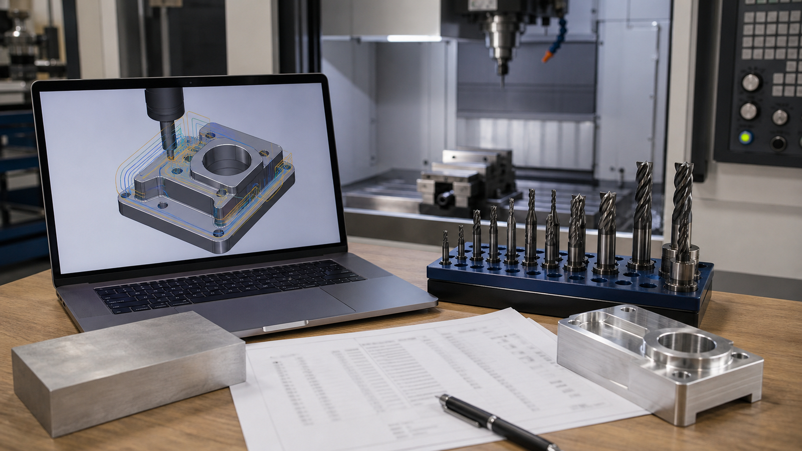
Step 2: Programming the Toolpaths (CAM)
Once the 3D model is finalized, it is imported into a new software environment called CAM, or Computer-Aided Manufacturing. This is where the virtual world meets the physical world. A skilled CAM programmer, or sometimes a highly experienced machinist, looks at the geometry of the part and decides exactly how to cut it out of a blank square block of metal.
The programmer has to choose which virtual cutting tools to use from a vast library of endmills, drills and face mills. They dictate the exact "toolpaths",the highways the tool will drive along while cutting. They set specific speeds (how fast the tool spins) and feeds (how fast the tool moves forward). A heavy, thick tool might be used first to rip away massive amounts of metal, followed by a tiny, delicate tool to trace out the small details.
At the end of this step, the CAM software translates all of these visual paths and settings into G-code. G-code is an incredibly long text file consisting of thousands of coordinates, telling the cutting machinery exactly where to go, line by line, millisecond by millisecond.
Before ever sending the G-code to the real machine, the CAM software runs a highly accurate digital simulation. This visually shows the programmer exactly how the metal will be cut in a 3D animation, guaranteeing that the tool will not accidentally crash into the holding clamps or gouge the part.
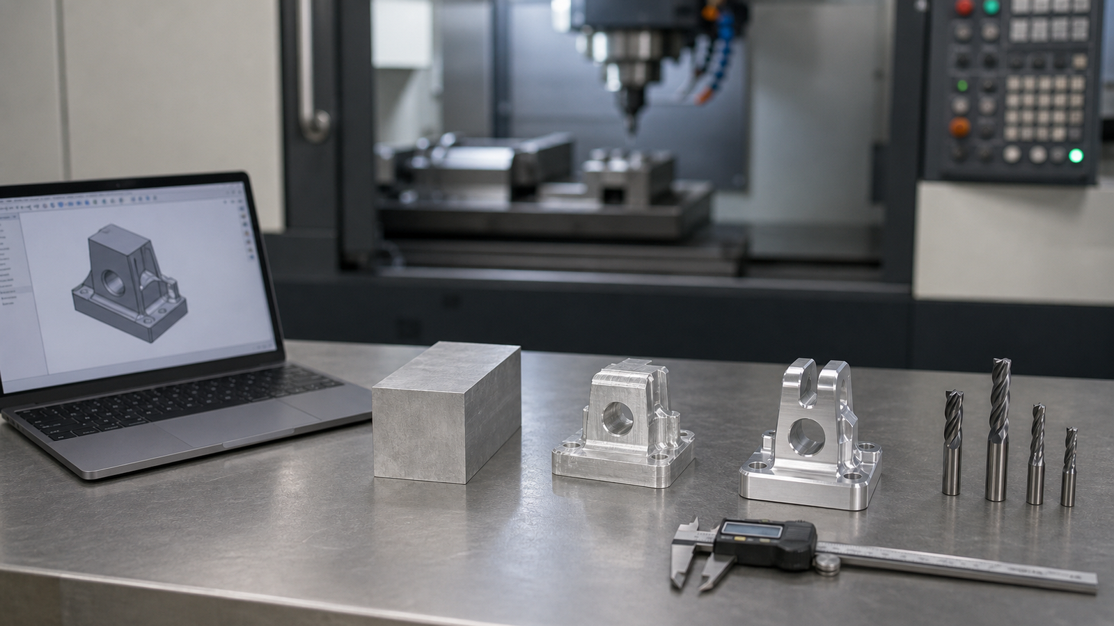
Step 3: Setting Up the Machine
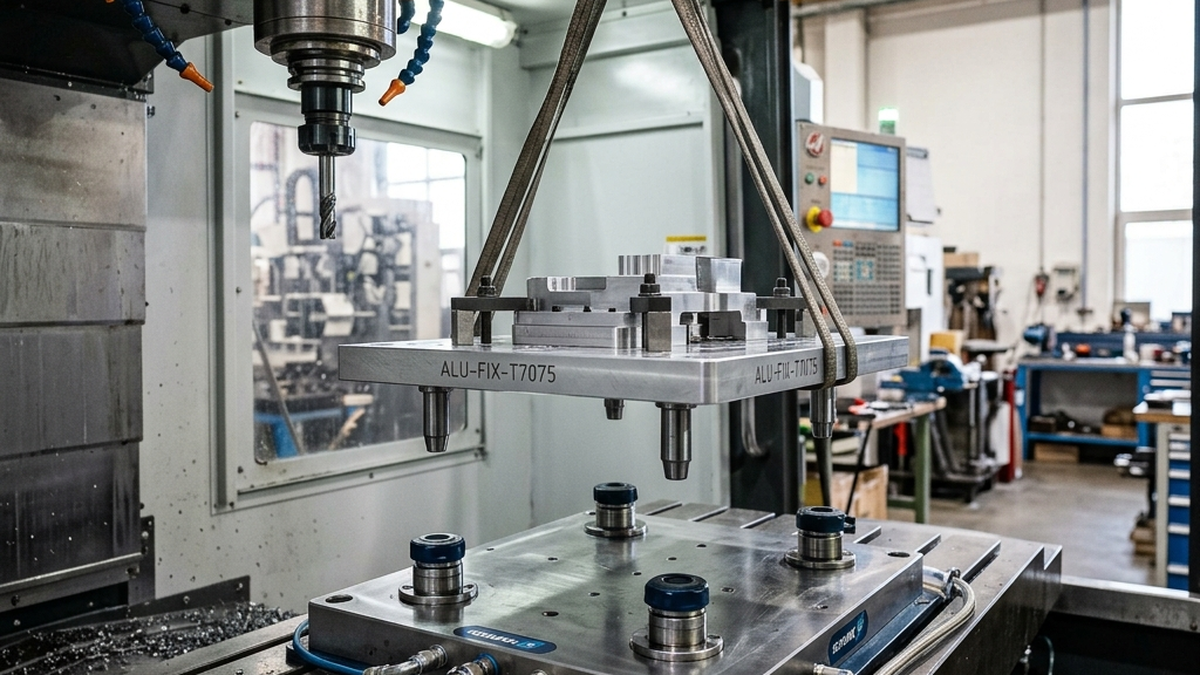
Now, the digital work stops and the physical labor begins. The machine operator steps up to the CNC machine. First, they must securely hold the raw material block (the workpiece). They place the metal block inside a heavy-duty steel vise or bolt it down to a custom holding fixture on the machine table. The grip must be tremendous. If the metal shifts even a fraction of a millimeter while being cut by a high-horsepower spindle, the entire part will be ruined and the cutting tool may shatter.
Next, the operator loads all the required cutting tools into the machine's automated tool carousel. They use an incredibly precise laser or touch probe to measure the exact length of every single tool down to a microscopic level. Finally, they use a similar touch probe to locate the exact top-left corner of the metal block. The machine now has a perfect zero-point to begin reading its G-code maps.
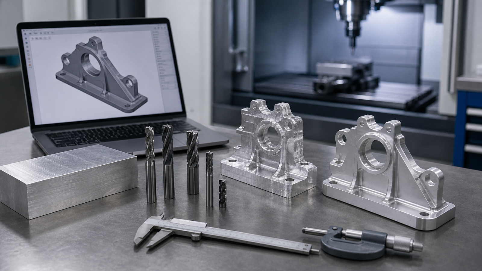
Step 4: Rough Cutting
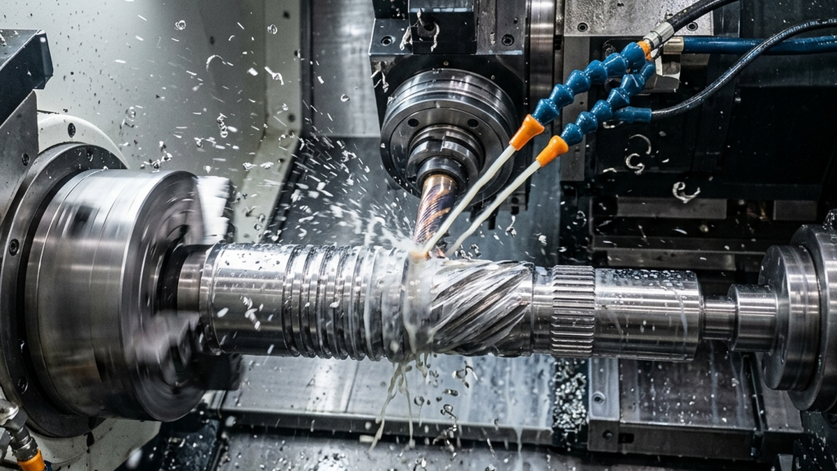
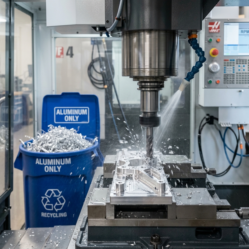
The operator presses the massive green start button and the CNC machine springs to life. The first major phase of cutting is called "roughing." During roughing, the only goal is to remove as much waste material as possible in the shortest amount of time. The machine grabs a large, very strong cutting tool.
Powered by motors the size of a car engine, the spindle plunges into the metal block. Heavy chips of hot metal fly everywhere, often washed aggressively away by a high-pressure stream of cooling fluid. The roughing phase leaves behind a part that looks like a blocky, jagged, staircase-like version of the final design. It leaves just a tiny, paper-thin layer of metal surrounding the true final shape, waiting to be smoothed out.
Step 5: The Finishing Passes
With the bulk of the waste gone, the machine automatically swaps the heavy roughing tool for a sharp, sleek finishing tool. The finishing phase is all about precision and creating a beautiful surface finish. The machine moves a bit slower now, allowing the sharp edges of the tool to gently shave away the final paper-thin layer of excess material.
If the part has complex, swooping 3D curves, a tool with a spherical tip (a ball mill) will run back and forth hundreds of times, blending the jagged stairs from the roughing phase into one perfectly smooth, continuous metal surface.
Step 6: Post-Processing and Deburring
Once the machine stops moving, the doors unlatch. The operator pulls the part out of the vise and washes off the slippery cutting fluids. However, the part is still not totally complete. When spinning tools cut metal, they often push a tiny, razor-sharp sliver of metal over the edge, creating what is known as a "burr."
A skilled worker carefully deburrs the part using hand files, specialized scraping edges, or motorized polishing wheels, ensuring every corner is safe to touch. In many cases, the part is then sent out to receive chemical treatments like anodizing, which dyes the metal a specific color and gives it a hard, protective outer shell against corrosion.
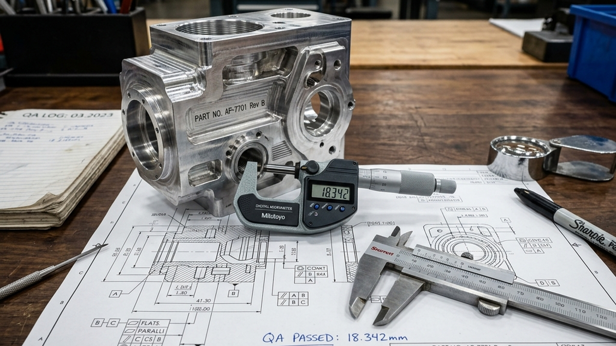
Step 7: Quality Assurance Inspection
The part looks finished, but the factory must prove it is perfect. If you want to understand what CNC machining is and why quality matters at every step, that article is a great starting point. The part transitions to the Quality Assurance (QA) room. A quality inspector uses highly calibrated measuring tools, such as digital micrometers, pin gauges for holes and calipers, to measure the key dimensions.
For complex aerospace or medical parts, they employ a Coordinate Measuring Machine (CMM). The CMM uses a tiny, sensitive ruby-tipped wand to physically touch the part in hundreds of different locations, building a highly accurate 3D map of the real-world object. The computer then compares this real-world map to the original CAD model. If every dimension aligns within the allowed rules (the tolerances), the part receives a passing grade. It is then carefully boxed in protective foam and shipped off to its final destination, bringing the digital dream fully into reality.
What to Look for in a Machine Shop
Not every machine shop is the right fit for every project. Before sending your CAD file, ask a few key questions. Does the shop have experience with your specific material? Cutting titanium for a medical implant is very different from cutting aluminum for a consumer gadget. A shop that primarily works in aluminum may struggle with exotic alloys.
Ask about their inspection equipment. A shop that owns a CMM can give you traceable, documented proof that your parts meet spec. For aerospace and medical projects, this is non-negotiable. For a simple bracket, a basic caliper check may be all you need.
Ask about lead times. Most prototype shops can turn around one-off parts in three to seven business days. Production runs of hundreds or thousands of pieces typically take two to four weeks. If you have a hard deadline, say so upfront. Shops can often prioritize your job for a small rush fee.
Finally, look at their communication style. A good shop responds quickly, asks smart questions about your design and flags potential problems before they cut a single chip. A shop that just takes your money and disappears until the parts ship is a shop that will surprise you with bad news at the worst time.
Common Mistakes to Avoid
Many first-time buyers make the same set of avoidable mistakes. Learning them early saves money and time.
The biggest mistake is sending a CAD file with no 2D drawing. A 3D model tells the shop the shape, but it does not tell them which dimensions are critical, what tolerances to hold, or what surface finish you expect. A 2D drawing with those callouts is essential for getting exactly what you need.
Another common mistake is putting tight tolerances on every dimension. Most surfaces on a typical part do not touch anything. They just exist. Calling out ±0.001 inch tolerances on those surfaces forces the shop to slow down and measure constantly, driving up cost with no benefit. Reserve tight tolerances for mating surfaces, bearing bores and other features that actually matter.
Last, many buyers forget to plan for post-processing time. If your parts need anodizing or powder coating, the shop sends them to a finishing house after machining. That adds three to five business days to your lead time. Plan for it.
Frequently Asked Questions
What exactly is CAM programming?
CAM (Computer-Aided Manufacturing) programming is the act of using advanced software to select tools, determine speeds and draw the paths that a cutting machine will follow. It turns a stationary 3D picture into millions of lines of active movement commands.
Why is part setup considered so critical?
The setup creates the foundation for every coordinate the machine executes. If the metal block is clamped slightly crooked, or if the starting zero-point is off by a hair, every single cut made by the machine will be perfectly executed in the completely wrong location.
How does a shop guarantee the finished part is correct?
Professional machine shops deploy dedicated quality inspectors who use microscopically accurate measuring devices like calipers and CMM probes to verify the physical metal shape against the engineer's original digital drawings.