Why Parts Don’t Fit
Every product around you, a laptop, a motor, a power tool, is made from precisely designed parts that have to mate together correctly across millions of units, manufactured on different days, by different machines, sometimes in different factories. A modern car engine has more than 30,000 individual components. A consumer laptop has hundreds of mating surfaces, from screw bosses in the chassis to precision hinge shafts. None of that works without a shared discipline.
That discipline is built on three concepts every mechanical engineer must understand: fits, tolerances and tolerance stackup analysis. Get them right and parts assemble first time. Get them wrong and you ship scrap, miss deadlines, or trigger a recall. This guide walks through what tolerances actually are, how to choose the right fit and how to verify that your assembly will work in production, not just in CAD.
Dimensions Are Meaningless Without Tolerances
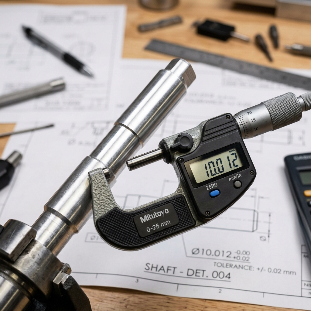
When you design in SolidWorks, Creo, NX, CATIA, or Fusion, you specify nominal dimensions, the “perfect” numbers. A shaft might be modeled as exactly 10 mm in diameter and the hole it slides into might also be 10 mm. On the screen that’s a perfect fit. In real production, nothing comes out exact. The hole might end up at 9.97 mm because of drill wear. The shaft might end up at 10.03 mm because of tool deflection. Now the “perfect fit” from CAD is an interference jam in real life.
That is why dimensions are meaningless without tolerances. A tolerance is the allowable variation around the nominal, the wiggle room you give the manufacturer. A callout of 10 ± 0.02 mm tells the shop that any part between 9.98 mm and 10.02 mm is acceptable; anything outside that range is out of spec and gets rejected. The combination of nominal + tolerance defines the size range that will actually exist in production. Without it, every part is theoretically perfect and practically a coin flip.
Process Capability: Match Tolerance to the Manufacturing Process
Different processes hold different tolerances. Before you write a single tolerance on a drawing, you have to ask what process will be used to make this part? Tightening a tolerance beyond what the chosen process can hold is the fastest way to make a design unmanufacturable.
Rough rules of thumb for one-shot capability (no extra finishing operations):
- Precision CNC turning (steel): ±0.0005” to ±0.001” (±0.013–0.025 mm) routinely.
- 3-axis CNC milling: ±0.002” to ±0.005” (±0.05–0.13 mm) on most features.
- Sheet metal bending: ±0.010” on bend angles and flat lengths.
- Injection molding: ±0.005” to ±0.010” (depends heavily on material shrinkage).
- Sand casting (aluminum): ±0.020” to ±0.040” or worse before any finishing.
Even within a single process, factors like tool wear, thermal drift, operator setup and machine calibration all shift the achievable tolerance. The honest answer is that any tolerance tighter than the “process-capable” range will require additional operations, grinding, honing, lapping, hand-fit, or 100% inspection and each of those operations costs real money. A ±0.0001” bore on a milled aluminum bracket isn’t free; it is a finish-grind operation hidden inside an innocent-looking number.

If your default block tolerance on the title block reads ±0.0005”, every dimension on the drawing inherits that, even the cosmetic ones. That single line in the title block can double the quote. Loosen the default to a process-capable value and tighten only on the features that need it.
Where to Tighten and Where to Loosen
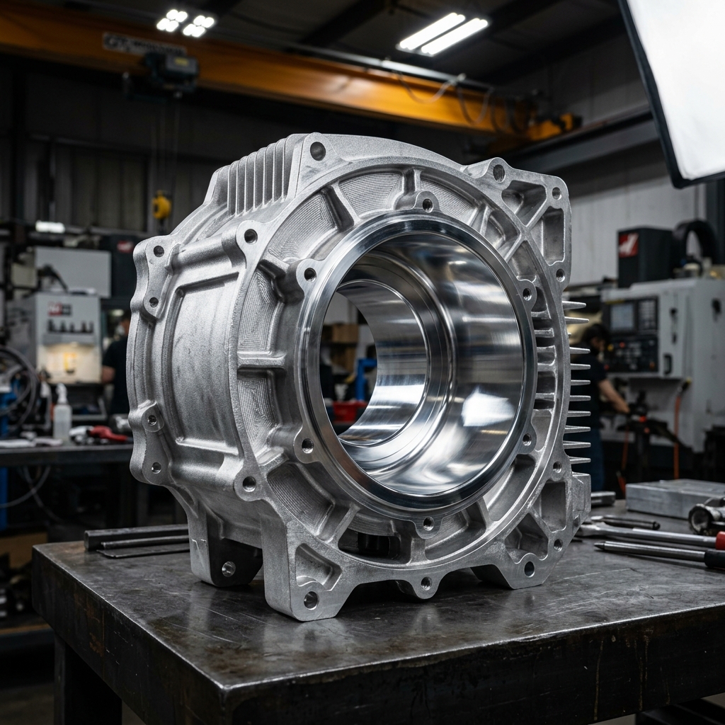
Take an aluminum motor housing for an electric scooter. It’s die-cast to form thin walls, ribs and mounting bosses that would be impossible or absurdly expensive to machine from billet. Applying CNC-level tolerances like ±0.0004” across the entire part fights the process, die casting naturally varies because of mold shrinkage and wear. The right move is to leave the cast surfaces loose and machine only the critical features: the bearing seat, the motor-alignment face, the bolt circle for the cover. Two operations, two tolerance regimes, one economical part.
The same logic applies to a fully machined part. On an aluminum gear housing, the bearing bores that support the gearbox shafts are critical, if they’re misaligned, the gears bind. Those bores should hold a tight position and diameter tolerance. The screw clearance holes 30 mm away on the same drawing? Standard ±0.005” is plenty. Holding the screw holes to the same precision as the bearing bores delivers zero functional benefit and a measurable cost increase. A seasoned engineer matches tolerance expectations to function, not to the title-block default.
The Three Engineering Fits
How two parts mate, a pin in a hole, a shaft in a bearing, two interlocking plastic clamshells, is described by a fit type. There are three.
- Clearance fit. The shaft is intentionally smaller than the hole, leaving a gap so the parts can move relative to each other. Used for rotating shafts in bushings, removable pins, sliding pulleys, anywhere motion is required.
- Transition fit. The tolerance bands of the shaft and hole overlap, so depending on the actual sizes a given pair might assemble with slight clearance or a light press. Used where alignment is important but you also need to be able to take the joint apart, locating dowels, gear-on-shaft assemblies that may need service.
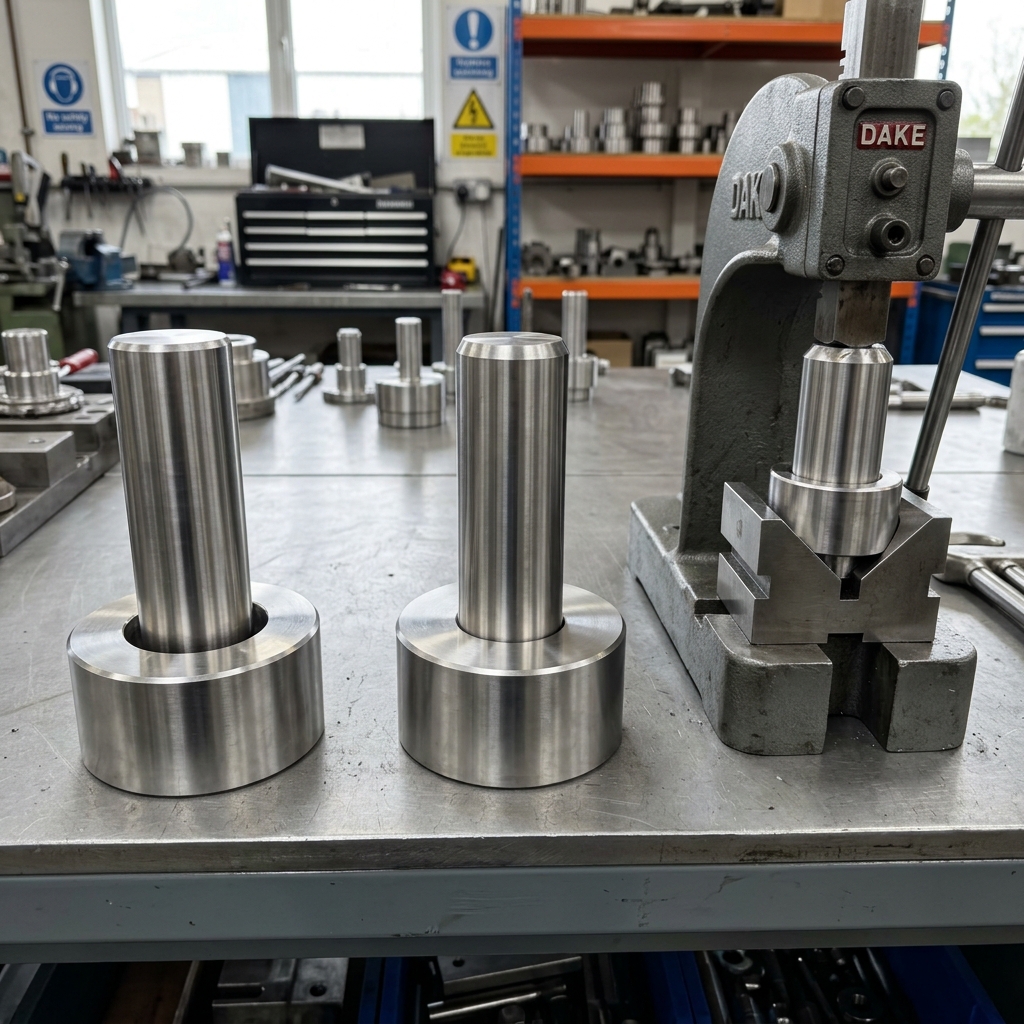
- Interference fit (press fit). The shaft is intentionally larger than the hole. Assembly requires force, heating the hub, or cooling the shaft. Once assembled, the joint behaves as a single unit. Used for press-fit bearings, gears that transmit torque without keys and structural press fits in shafts and pulleys.
Picking the wrong category is a category error: a slip fit where you needed a press fit lets the gear spin freely on the shaft instead of transmitting torque. A press fit where you needed a slip fit means a $5 bushing requires a 10-ton arbor press to install. The fit type is the first decision; the tolerance numbers come second.
ANSI vs ISO Fit Standards
Once you’ve picked a fit category, you don’t calculate the limits from scratch. Standards committees have already done it. Two systems dominate.
ANSI B4.1 (used in the US) describes fits with two-letter codes followed by a number that signals tightness:
RC, Running & sliding clearance fit (RC1close,RC9loose)LC,LT,LN, Locational clearance, transition and interference fitsFN, Force fit (FN1light drive,FN5heavy shrink)
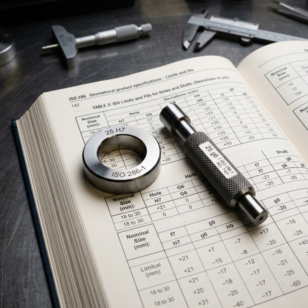
ISO 286 (used globally) describes fits with one letter plus a grade number for the hole and one for the shaft. Capital letters apply to holes, lowercase to shafts. Common combinations:
H7/h6, Sliding fit, very small clearance, used for locating with rotation possibleH7/g6, Free running fit with small clearance, classic shaft-in-bushingH7/k6, Light transition fit for locating dowelsH7/p6, Press fit for permanent assembliesH7/s6, Heavy shrink fit for high-torque transmission
Once you know the nominal size and the desired fit class, the standard tables give you the exact upper and lower limits for both hole and shaft. This is faster than calculating, more reliable than guessing and, critically, standardized across shops, so a CNC vendor in Texas, a bushing supplier in Germany and a bearing maker in Japan all interpret Ø25 H7 the same way.
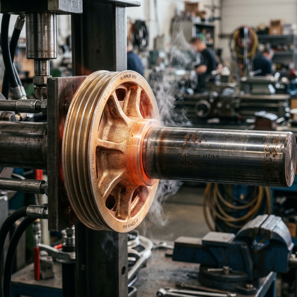
Worked Example: Steel Shaft into Aluminum Hub
Suppose we’re mounting a steel shaft into an aluminum pulley hub used in an automotive belt drive. Nominal diameter is 1.98”. We need a firm, non-slip interference fit so the pulley can transmit torque under heavy load without ever rotating on the shaft.
Using ANSI B4.1 we pick an LN2, a locational interference fit, considered a true interference. For a 1.9”-class nominal, the standard table gives us roughly:
- Hole: 1.9800” to 1.9812”
- Shaft: 1.9814” to 1.9821”
- Resulting interference: 0.0002” to 0.0021”
That tells us several practical things about the assembly process. First, even a few ten-thousandths of an inch determine whether the parts go together at all, this is not a part you assemble with a rubber mallet. Second, with an aluminum hub on a steel shaft, the right assembly method is thermal: heat the hub to expand the bore, drop the cold shaft in, let it cool. Third, if the interference creeps above the upper limit, the aluminum hub can yield and lose its grip permanently, so the upper-limit shaft tolerance is functional, not cosmetic.
None of those decisions are visible if you write “Press Fit, see assembly drawing” on the print. Spelling out the limits in the standard’s notation tells everyone, the machinist, the inspector, the assembly tech, exactly what the part has to be.
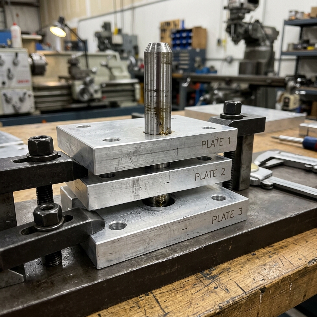
Why Good Parts Still Fail to Assemble
Even when every part in your design individually meets its tolerance, assemblies often still fail. The reason is tolerance stackup: the accumulated variation along a chain of dimensions can exceed the gap or feature it needs to fit into, even when no individual dimension is out of spec.
Imagine a portable bidet whose fluid canister slides into the device body. Each dimension on each part is within its individual tolerance. But if several of those dimensions happen to be at their upper limits at the same time, the green cap on the canister protrudes past the sliding surface of the body and the assembly jams. Now imagine that failure on a production line at 100,000 units per quarter, or worse, on units that have already shipped to customers. The result is scrap, rework and recalls, all of which were predictable from the dimension chain on day one.
Tolerance stackup analysis is the calculation that catches this before tooling. It traces the chain of dimensions from one critical surface to another, sums the contributing tolerances and reports whether the assembly will actually close in the worst case, or in 99.7% of cases, depending on the method you use.
Worst Case, RSS and Monte Carlo
There are three common methods for evaluating a stackup and they give very different answers from the same input.
Worst case assumes every dimension in the chain is simultaneously at its extreme limit, all biggest, or all smallest. It guarantees the assembly works under any conceivable condition. It is also the most pessimistic method and often forces unnecessarily tight tolerances that drive cost without changing the field result. Worst case is the right call for safety-critical and life-support assemblies where any failure is unacceptable.
Root sum square (RSS) treats the dimensional variations as random and statistically independent. Instead of adding the tolerances directly, it adds them as the square root of the sum of their squares. The result is the standard deviation of the assembly variation; multiply by 3 to get the ±3σ (~99.7%) prediction. RSS is the right call for most consumer and industrial assemblies because the probability of every dimension hitting an extreme at the same time is vanishingly small. It typically lets you loosen tolerances 30–50% versus worst case while still hitting the same yield.
Monte Carlo simulation goes one step further. The CAD tool runs thousands of virtual builds, randomly sampling each dimension from its tolerance distribution and produces a histogram of assembly outcomes. You can read off the predicted yield directly: “94.6% of units will assemble.” For high-volume production, Monte Carlo gives a probabilistic view of yield instead of a binary pass/fail, which is what your operations team actually cares about.

Use worst case when failure is unacceptable (medical, aerospace life support). Use RSS when you can tolerate a small statistical reject rate. Use Monte Carlo when you want to see the yield distribution and target a specific Cpk on the assembly.
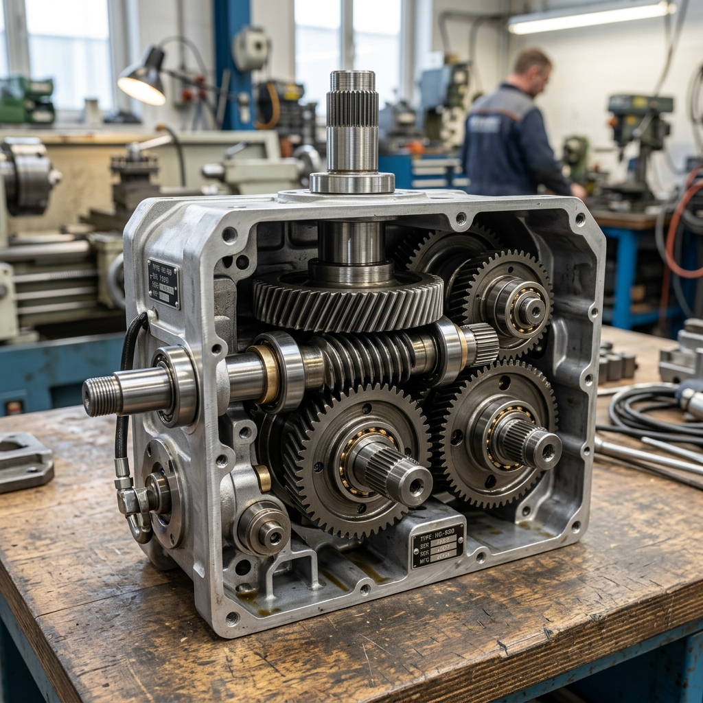
Worked Example: Gearbox Center-Distance Stackup
Take a hand-cranked gearbox. The input shaft drives a helical gear that meshes with a worm gear on the output shaft. Mesh quality, whether the gears bind, whether the backlash is acceptable, depends on the center-to-center distance between the worm axis and the helical gear axis. That center distance is set by a chain of dimensions: the gear-frame web thickness, the bushing OD, the bushing-bore concentricity, the gear-bore-to-OD runout and so on.
If that chain shifts, the worm and helical gear bind on the high side or develop excessive backlash on the low side. The hand crank either becomes hard to turn or skips under load. None of that shows up in CAD because CAD assumes nominal everything.
In SolidWorks TolAnalyst (or any equivalent tool, CETOL, 3DCS, Inspire, Geometric’s DCS) the workflow is the same:
- Define the datums, the surfaces every dimension is measured from.
- Define the dimensions and tolerances along the chain until it’s fully constrained.
- Pick the measurement, in our case, the worm-to-helical center distance.
- Select the components in the order they assemble.
The tool then reports the worst-case minimum and maximum, the RSS prediction and, this is the most useful output, the contribution percentage of each dimension to the total variation. If the bushing OD tolerance is contributing 60% of the stackup and the gear-frame web is contributing 5%, you know exactly where to spend your next tolerance dollar.
Before tolerance analysis software, this was a spreadsheet exercise. Engineers traced dimension chains by hand, applied plus/minus limits and computed extremes one row at a time. It worked, it was slow and it was error-prone for assemblies with hundreds of parts. Modern CAD tools do this in seconds. There is no excuse not to run a stackup on every assembly that depends on a closing gap, a meshed pair, or a sliding fit.
The Precision-Fit Design Workflow
Pulling all of this together, here is the six-step workflow that produces parts which assemble first time:
- Identify the manufacturing process for each part and document its capability range. Every tolerance decision downstream rests on this.
- Define the functional requirements. Which features actually affect assembly and performance? Mark them. Everything else gets the standard block tolerance.
- Apply standard fits from ANSI B4.1 or ISO 286 to mating features based on the intended function (running, locating, press, shrink). Don’t invent fits when a standard exists.
- Assign tolerances appropriately. Tighten only where critical; loosen everywhere else. Refuse the temptation to make every dimension ±0.0005”.
- Run a tolerance stackup analysis on every closing gap or critical assembly relationship. Use worst case for safety-critical, RSS or Monte Carlo for everything else.
- Iterate. Identify the dimensions that drive the most stackup variation and tighten those first. Loosen the dimensions that don’t move the needle. Re-run.
Skipping any of these is the express route to assembly failure. Doing all six is the difference between a first-run yield of 60% and 99% and the difference between a quote that ships on time and one that comes back twice for rework.
The smallest details in tolerance control often make the biggest difference in product quality. Engineers who design assemblies that fit perfectly on a first production run save companies enormous time, money and rework. Before you finish your next design, ask yourself: have I chosen the right fits, are my tolerances achievable and will it still assemble when every part is at its worst limit? Upload your CAD and find out before tooling.
Frequently Asked Questions
What is the difference between a dimension and a tolerance?
A dimension is the nominal or “perfect” value an engineer enters in CAD, for example, a 10 mm shaft diameter. A tolerance defines the acceptable variation around that nominal, for example, 10 ± 0.02 mm. In the real world, no machined part comes out exactly to the nominal, which is why dimensions are meaningless without tolerances.
What are the three main types of engineering fits?
Clearance fits intentionally leave a gap so parts can move freely (rotating shafts, sliding pins). Transition fits sit on the boundary, depending on actual sizes, the assembly may have slight clearance or a light press, used where alignment matters but the joint may need to be removed. Interference fits intentionally make the shaft larger than the hole, so assembly requires force, heat, or cooling, used for press-fit bearings, hubs and gears that must transmit torque without slipping.
What is tolerance stackup analysis?
Tolerance stackup analysis is a calculation that combines all the individual dimension tolerances along an assembly chain to predict the total variation at a critical gap, distance, or fit. Even when every part is individually within spec, the accumulated variation can cause assemblies to fail. The three common methods are worst-case (assume every dimension is at its extreme limit simultaneously), root sum square (statistically combine the variations) and Monte Carlo simulation (run thousands of randomized virtual builds).
What is the difference between worst case and RSS tolerance analysis?
Worst-case analysis assumes every dimension in the chain is simultaneously at its tightest or loosest limit, it guarantees the assembly works under any condition, but often forces unnecessarily tight (and expensive) tolerances. Root sum square (RSS) treats variations as random and statistically independent and combines them as the square root of the sum of their squares. RSS gives a more realistic estimate for production runs because hitting all limits at once is statistically unlikely. Monte Carlo simulation goes further by running thousands of random builds and producing a yield distribution.
How tight should I make my CNC tolerances?
Only as tight as the function actually requires. Default to standard process tolerances (roughly ±0.005” for milled features, ±0.002” for turned features) and tighten only on functional surfaces such as bearing bores, mating faces and dowel pin holes. Tightening every dimension to ±0.0005” can multiply machining and inspection cost without improving how the assembly performs.
What is an H7/g6 fit?
H7/g6 is a standard ISO sliding fit. The capital letter H7 describes the tolerance zone for the hole (H7 means the lower limit equals the nominal, with a tolerance band of grade 7). The lowercase g6 describes the shaft (g6 means the upper limit is just below the nominal, with grade 6 tolerance). The combination produces a small, predictable clearance that allows free rotation while keeping the shaft well-aligned in the hole.