How Vacuum Fixturing Works
A vacuum fixture uses air pressure to hold parts flat. A pump removes air from under the part. Atmospheric pressure pushes down on top. The part stays put with no clamps touching it.
The fixture has a flat surface with channels or holes connected to a vacuum pump. You place the part on top. A rubber seal around the edge keeps air from leaking in. The pump pulls a vacuum and the part locks down.
Vacuum fixturing gives you full access to the top surface. No clamps in the way. No jaw marks. No distortion on thin parts.
Holding Force Calculations
The math is simple. Full vacuum gives you about 14.7 psi of hold-down pressure. Multiply that by the sealed area to get total force.
Hold-down force (lbs) = Sealed area (sq in) x 14.7 psi. Lateral force = Hold-down force x friction coefficient (0.3 for aluminum, 0.5 for steel).
| Part Size | Sealed Area | Hold-Down Force | Lateral Force (Aluminum) |
|---|---|---|---|
| 4" x 4" | 16 sq in | 235 lbs | 71 lbs |
| 6" x 6" | 36 sq in | 529 lbs | 159 lbs |
| 8" x 8" | 64 sq in | 941 lbs | 282 lbs |
| 12" x 12" | 144 sq in | 2,117 lbs | 635 lbs |
These numbers assume a perfect seal. Real-world holding force is 70-85% of the theoretical maximum. Always test with a light cut first.
Material Limits
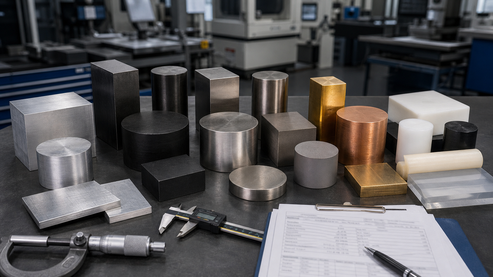
Vacuum works great on some materials. It fails on others. The key factor is porosity. Air cannot leak through the part.
- Works well: Aluminum, steel, brass, copper, solid plastics (Delrin, acrylic, PEEK)
- Won't work: Cast iron, sintered metals, porous ceramics, wood, foam
- Use caution: Very thin sheet metal (can flex and break seal), parts with through-holes
If your part has holes from a previous operation, you must plug or tape them. One open hole can break the entire vacuum seal.
Seal Design Tips
The seal is the most important part of a vacuum fixture. A bad seal means low holding force. Here is how to get it right.
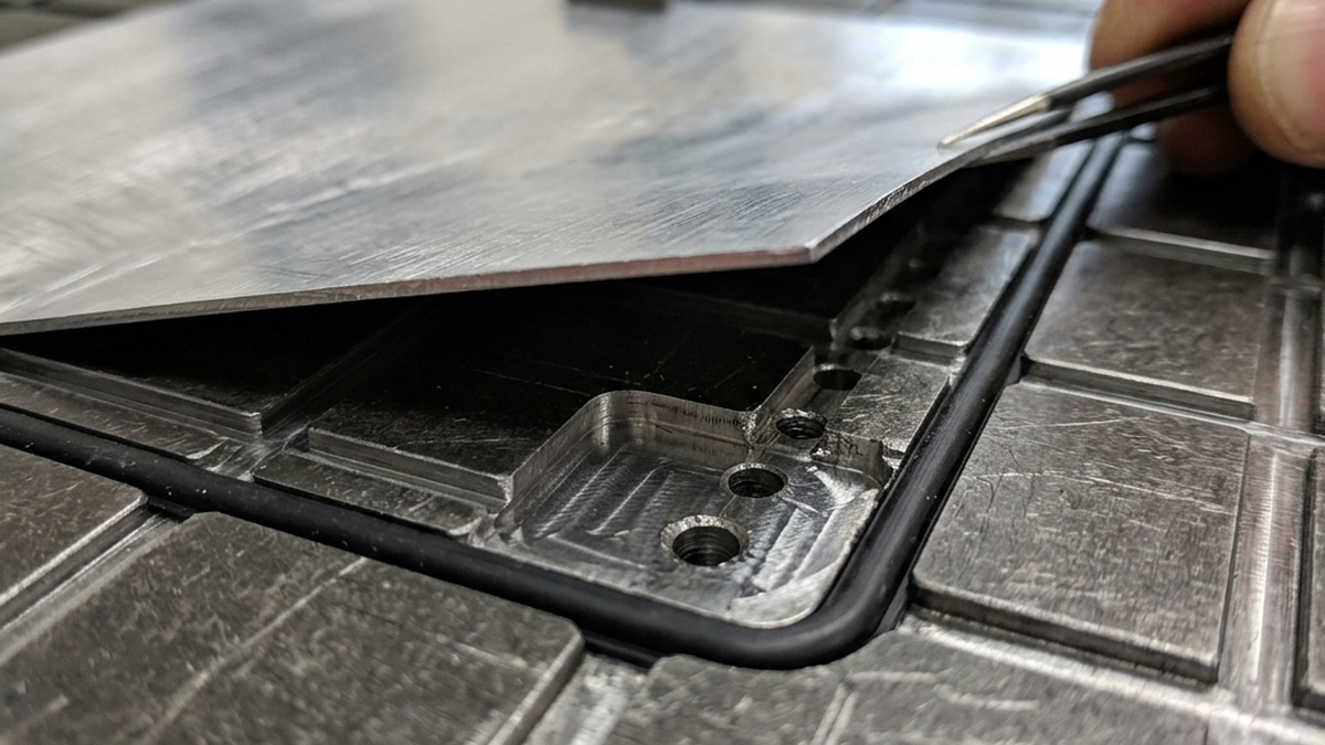
- O-ring grooves, Machine a groove around the part pocket. Insert a rubber O-ring. This is the most reliable seal method.
- Foam tape, Closed-cell foam tape works for quick setups. Replace it often. It compresses and loses seal over time.
- Gasket material, Cut a custom gasket from neoprene sheet. Good for odd shapes.
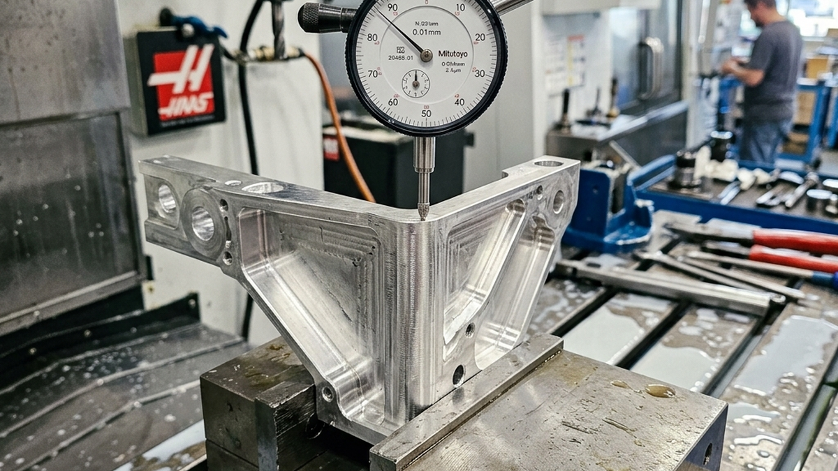
- Surface flatness, The fixture surface must be flat within 0.001". Any bow breaks the seal at the edges.
When Vacuum Beats a Vise
Vacuum is not a replacement for a vise. It is a tool for specific jobs. Here is when vacuum wins.
- Thin parts under 0.100", A vise will distort these. Vacuum holds them flat with zero clamping stress.
- Full top-surface access, No clamps means the cutter can reach every feature on the top face.
- Large flat panels, Parts bigger than your vise opening are easy on a vacuum table.
- Engraving and marking, Very light cuts with full surface access.
For everything else, a vise or fixture gives you more holding force and handles heavier cuts.
Best Practices
- Always test the seal. Turn on the vacuum and try to slide the part. If it moves easily, fix the seal before cutting.
- Use light cuts. Take shallow passes with low feed force. Save heavy roughing for a vise setup.
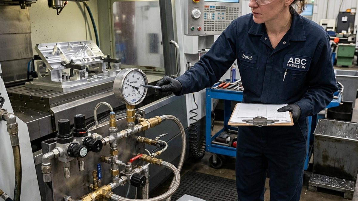
- Monitor vacuum pressure. A gauge on the pump shows you if the seal is holding. Watch for drops during cutting.
- Keep surfaces clean. Chips and oil under the part break the seal. Blow the fixture clean before each load.
- Use a sacrificial spoil board. Machine slightly into the fixture surface. This is safer than cutting into the vacuum plate itself.
Struggling with thin-wall distortion? Upload your CAD file and our team will recommend the best fixturing approach for your part.
The Reality of Vacuum Holding Force
Vacuum fixturing works because atmospheric pressure pushes the part against the fixture when air is removed from the sealed area. The basic calculation is simple: holding force equals pressure differential times sealed area. In ideal sea-level conditions, a perfect vacuum could approach 14.7 pounds per square inch. Real CNC fixtures are lower because pumps do not pull a perfect vacuum, seals leak, coolant gets under the part and surface texture reduces contact.
That means a 4 square inch sealed area is not the same as a 40 square inch sealed area. Small parts can be risky because they do not have enough area to generate meaningful hold-down force. Thin plates, covers and panels are better candidates because they often have broad flat surfaces. This is why buyers searching for vacuum fixture holding force calculation for CNC should treat the formula as a starting point, not a promise.
Cutting force matters too. Vacuum primarily resists lift and sliding through friction. Aggressive side cutting, heavy slotting or interrupted cuts can overpower a weak vacuum setup. For thin-wall parts, shops often combine vacuum with light mechanical stops, dowel pins or sacrificial tabs to control lateral motion without distorting the part.
How to Design Parts for Vacuum Fixturing
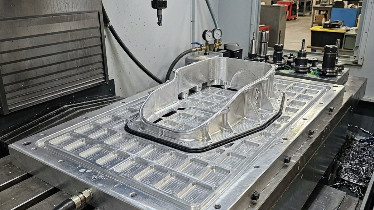
The best vacuum-fixtured parts have a continuous sealing land. A gasket needs an uninterrupted path around the vacuum zone. If the bottom of the part has pockets, holes, slots or ribs, the shop may need a custom fixture plate with isolated zones. The more the fixture has to route vacuum around features, the more setup time and leak risk increase.
Flatness matters. A bowed blank may leak before machining even begins. For sheet or plate parts, it can help to leave extra stock and rough both sides before final finishing. For very thin parts, the shop may machine one side, stress relieve or flip carefully, then finish with vacuum support to avoid clamp distortion.
Vacuum is also useful for cosmetic parts because it avoids clamp marks on visible faces. However, it is not a magic answer for every thin part. If the part is small, porous, heavily pocketed or requires aggressive roughing, a hybrid fixture may be better. That is why vacuum fixturing for thin wall aluminum parts often goes hand in hand with secondary support features.
Long-Tail Questions This Article Answers
This article covers vacuum fixturing for thin wall CNC parts, how to calculate vacuum hold down force, vacuum workholding for aluminum sheet machining, when vacuum beats a vise in CNC machining, seal design for CNC vacuum fixtures, vacuum fixture limits for small parts, preventing distortion in thin plate machining and hybrid vacuum fixture with pins and stops.
If the part has a large flat underside, vacuum may be the cleanest setup. If it is small or interrupted by holes, ask the shop to review holding force before committing to the process.
What to Share Before a Vacuum Fixture Is Designed
Send the full model, not just a drawing screenshot. The shop needs to inspect the underside, holes, pockets and sealing surfaces. If the part has breaks in the sealing path, the fixture may need multiple vacuum zones, gasket grooves or support islands.
Share flatness requirements and stock condition. A thin plate that arrives warped may not seal reliably until it is rough-machined. If the final part has a cosmetic surface, tell the shop which side must be protected. Vacuum may be selected specifically to avoid visible clamp marks.
Also ask how the shop will resist side loads. Pins, edge stops, tabs or light clamps may be added without defeating the purpose of vacuum. A fixture that handles both vertical holding and horizontal cutting force will be much more reliable.
Common Vacuum Fixturing Mistakes to Avoid
A common mistake is assuming vacuum works on any flat-looking part. Porous material, interrupted sealing surfaces and small contact area can make vacuum unreliable. Another mistake is ignoring side loads. Vacuum may hold a part down but still allow sliding if the cutter pushes laterally. The third mistake is skipping leak checks. A fixture that holds during dry setup may leak once coolant, chips and thermal change enter the process.
For best results, send the shop the model, drawing, quantity, revision status, target lead time and any inspection or documentation requirements at the start. Clear inputs help the supplier quote the real job, choose the right setup and avoid surprises after machining begins.
Final Buyer Takeaway
The best machining outcome usually comes from matching the quote package to the real manufacturing risk. A simple bracket may only need a clean model, standard material and normal inspection. A thin, cosmetic, regulated or schedule-critical part needs more context. Share the part function, mating features, quantity forecast, finish expectations and the reason any tight tolerance exists. That information lets the shop recommend a practical process instead of guessing from geometry alone.
For SEO and answer-engine clarity, this article intentionally addresses specific buyer searches rather than broad definitions only. Those long-tail questions are often the same questions a manufacturing engineer asks before releasing a purchase order: how will the part be held, what records are required, how will cost change at quantity and which risks should be solved before the first chip is cut?